
Arc monitoring and protection system based on pressure protection

An arc light and pressure technology, which is applied in the direction of emergency protection circuit devices, electrical components, substation/distribution device shells, etc., can solve problems such as failure to realize protection, failure of current overcurrent protection module, interference of arc light monitoring module, etc., to achieve Avoid visible light interference, effective protection, avoid secondary damage

Pending Publication Date: 2018-07-10
北京海智元科技有限公司
View PDF0 Cites 2 Cited by
  • Summary
  • Abstract
  • Description
  • Claims
  • Application Information

AI Technical Summary

Problems solved by technology

[0004] There are four disadvantages in this method of arc monitoring and protection: first, the arc monitoring module is easily interfered by light sources such as visible light, and sends out false alarm signals; second, the current overcurrent protection module does not consider the load change, resulting in peak-to-peak distortion of the current waveform, resulting in false alarms Or do not report. In addition, if the fault arc in the power distribution cabinet is a series arc, it is intermittent, the light intensity is low, and the energy of the arc light is mainly concentrated in the ultraviolet band of 300-400nm. If it is not dealt with, it will exist for a long time. However, due to the low light intensity and low energy of the series arc, it may not be able to produce obvious distortion of the peak-to-peak value of the current waveform, thus resulting in false alarms for the series arc; third, the tripper has a long operating cycle and cannot achieve effective protection; four. It is that when the arc explosion occurs, it cannot effectively restrain its secondary damage to the surrounding personal and property

Method used


Image

  • Arc monitoring and protection system based on pressure protection

Examples


Embodiment Construction

[0021] The present invention will be described in detail below with reference to the accompanying drawings and examples.

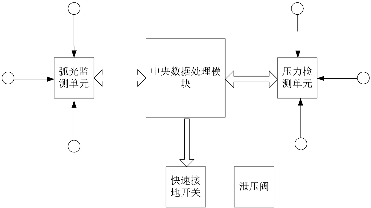
[0022] Please refer to figure 1 , figure 1 A block diagram of the composition of the pressure protection-based arc monitoring and protection system provided by the embodiment of the present invention is shown.

[0023] The system is set in a closed power distribution cabinet; the device includes: an arc sensor, a pressure sensor, a quick grounding switch and a central processing module.

[0024] The arc light sensor is an optical fiber cable, and the arc light sensor is laid serpentinely in the power distribution cabinet; in the embodiment of the present invention, the optical fiber cable generally chooses POF (polymer optical fiber) to meet the arc light monitoring requirements. If the cost is not considered, SOF (quartz Optical fiber) can achieve a light transmittance of more than 99% and an attenuation rate of less than 20Db / km.

[0025] The pressure...


PUM


Abstract

The invention discloses an arc monitoring and protection system based on pressure protection, which can accurately and effectively detect an arc in a medium-high voltage DC enclosed power distributioncabinet, thereby realizing effective protection. The technical scheme of the invention is that an arc sensor is a fiber optic cable, and the arc sensor is serpentinely laid in the power distributioncabinet; and a pressure sensor is a monocrystalline silicon pressure switch, and the pressure sensor is arranged in a multi-point redundant manner inside the power distribution cabinet. A quick grounding switch is arranged in an outlet circuit of the power distribution cabinet. An arc signal processing unit acquires an arc signal from the arc sensor, determines whether an arc occurs in the power distribution cabinet, and sends a determination result to a DSP processor. A pressure signal processing unit obtains a pressure signal from the pressure sensor to determine whether a sudden increase inpressure occurs in the power distribution cabinet, and sends a determination result to the DSP processor. The DSP processor makes an AND logic decision and, if a fault arc occurs in the power distribution cabinet and the pressure in the power distribution cabinet suddenly increases, sends a grounding command to the quick grounding switch to control the grounding of the quick grounding switch.

Description

technical field [0001] The invention relates to the technical field of arc protection for medium and high voltage DC power distribution cabinets, in particular to an arc monitoring and protection system based on pressure protection. Background technique [0002] At present, most of the power equipment protection devices widely used in the fields of ships, petrochemicals, and electric power are arc monitoring and current overcurrent monitoring and logic controllers. not good. [0003] The traditional arc protection device consists of four modules: arc monitoring module, current overcurrent protection module, logic controller and circuit breaker actuator. The arc monitoring module collects arc signals through photosensitive sensors, and the current overcurrent protection module outputs abnormal signals when the instantaneous current value reaches several times the normal current value. The outputs of the above two modules are connected with the logic controller to output arc ...

Claims


Application Information

Patent Timeline
IPC IPC(8): H02H7/22H02B1/30
CPCH02B1/306H02H7/22
Inventor 马守军徐定海刘洪鹏陈小东李卓明
Owner 北京海智元科技有限公司
Learn More