
Switching device and inflating device for free piston shock tunnel compression pipe

A technology of shock tunnel and transfer device, which is applied in the direction of measurement device, pipe/pipe joint/pipe fitting, connection with fluid cut-off device, etc., can solve the problems affecting the flow field of the wind tunnel, etc. High vacuum suction is difficult, and the effect of meeting the needs of various operating states

Active Publication Date: 2018-07-13
CHINA ACAD OF AEROSPACE AERODYNAMICS
View PDF7 Cites 7 Cited by
  • Summary
  • Abstract
  • Description
  • Claims
  • Application Information

AI Technical Summary

Problems solved by technology

At the same time, before filling helium and argon, the compression tube needs to be evacuated first. Due to the large volume of the compression tube, if you want to pump to a relatively low vacuum, you need to open a relatively large suction port, which will inevitably affect flow field in wind tunnel
In this way, two problems need to be solved: 1, the high-precision ratio problem of helium and argon in different operating modes, and 2, the high vacuum suction problem of the compression tube

Method used


Image

  • Switching device and inflating device for free piston shock tunnel compression pipe
  • Switching device and inflating device for free piston shock tunnel compression pipe

Examples


Embodiment

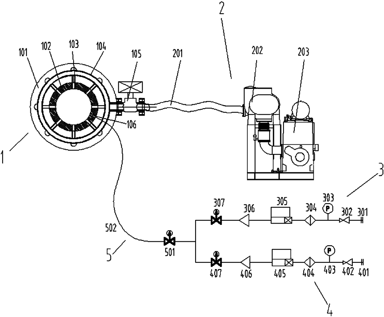
[0055] A compression tube inflation device adapting to various operating states of a free piston shock tunnel such as figure 1 As shown, it consists of an adapter device 1, a vacuum system 2, a helium filling branch 3, an argon filling branch 4, and a summary gas path 5.

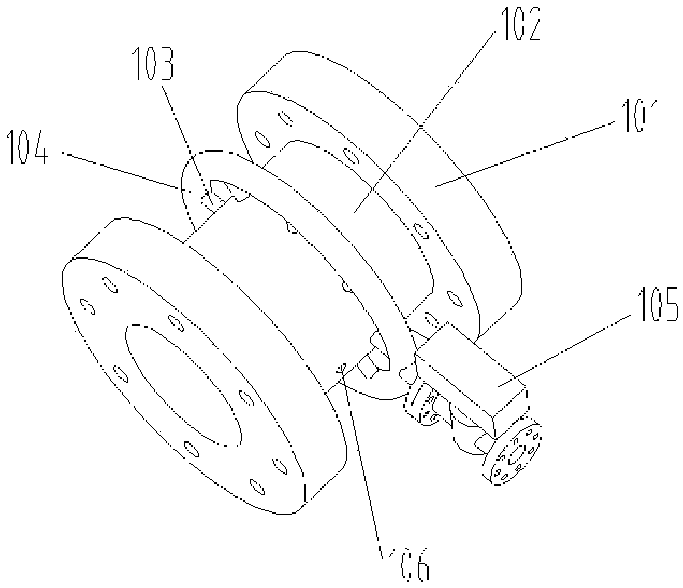
[0056] Such as figure 1 , figure 2 As shown, the adapter device 1 includes a flange 101, a pipe body 102, a suction column 103, a suction ring 104, and a first high-pressure pneumatic valve 105, and an air charging port 106 is provided on the pipe body. The suction column 103 is connected to the pipe body by welding, and then connected to the suction ring 104 by welding, and the suction ring 104 is connected to the first high-pressure pneumatic valve 105 through a flange. This structure improves the flow conductance of the vacuum suction pipeline, so that the compression tube can be sucked to a lower vacuum before helium and argon are inflated, ensuring the purity of the gas in the compression tube. The ...


PUM


Abstract

The invention relates to a switching device and an inflating device for a free piston shock tunnel compression pipe and belongs to the technical field of hypersonic speed shock tunnel engineering. According to the switching device and the inflating device, the switching device is additionally arranged in a wind tunnel structure; the problem that high-vacuum extraction of the free piston shock tunnel compression pipe is difficult to conduct is solved, and thus the gas purity is improved; and the charging ratio of helium gas to argon gas is controlled through a flow controller, the charging ratio precision is improved, and thus the requirement for multiple operation states of the free piston shock tunnel is met.

Description

technical field [0001] The invention relates to an adapter device and an inflating device for a compression tube of a free piston shock wave wind tunnel, belonging to the technical field of hypersonic shock wave wind tunnel engineering. Background technique [0002] The free piston shock wave tunnel is mainly composed of high-pressure gas storage chamber (including heavy piston launch mechanism), compression tube, first diaphragm, shock tube, second diaphragm, nozzle, test section and vacuum box and other main components. [0003] The operating principle is to launch a heavy piston through a high-pressure gas storage chamber, and the heavy piston pushes the light driving gas (helium or helium / argon mixed gas) of the compression tube to make it reach the set high temperature and high pressure state, and drive it Shock tube running. The Free Piston Shock Tunnel is currently the most feasible device for obtaining high-density hypersonic / ultra-high-speed test airflow. The alti...

Claims


Application Information

Patent Timeline
IPC IPC(8): F17D1/02F17D3/01F16L23/02F16L25/00F16L29/00G01M9/00
CPCF16L23/02F16L25/0036F16L29/00F17D1/02F17D3/01G01M9/00
Inventor 宋可清陈星谌君谋王玉东李辰毕志献蒋博马雁捷
Owner CHINA ACAD OF AEROSPACE AERODYNAMICS
Learn More