Microwave photon MIMO radar detection method and microwave photon MIMO radar system

A microwave photon and radar system technology, applied in the field of microwave photon radar detection, can solve the problems of large coherent processing interval, long measurement time, radar target detection ability decline, etc., to achieve real-time signal processing, high radar azimuth resolution, high radar Effect of distance resolution

Active Publication Date: 2018-07-17
NANJING UNIV OF AERONAUTICS & ASTRONAUTICS
View PDF5 Cites 36 Cited by
  • Summary
  • Abstract
  • Description
  • Claims
  • Application Information

AI Technical Summary

Problems solved by technology

Although the introduction of microwave photonics technology can obtain high-carrier frequency and large-bandwidth transmission signals, which improves the range resolution of radar (see [F. Zhang, Q. Guo, and S. Pan, "Photonics-based real-time ultra-high -range-resolution radar with broadband signal generation and processing,"Sci.Rep.,7,13848,(2017).]), but the azimuth resolution of the radar needs to be achieved by the relative rotation of the target and the radar, which means that a large Coherent Processing Interval (CPI) or long measurement time is required to obtain high azimuth resolution
In the practical application of detecting non-cooperative targets whose motion trajectory and parameters are unknown, this is not always feasible, because the fluctuation of the target's velocity and attitude will degrade the target detection ability of the radar

Method used


Image

  • Microwave photon MIMO radar detection method and microwave photon MIMO radar system
  • Microwave photon MIMO radar detection method and microwave photon MIMO radar system
  • Microwave photon MIMO radar detection method and microwave photon MIMO radar system

Examples


Embodiment Construction

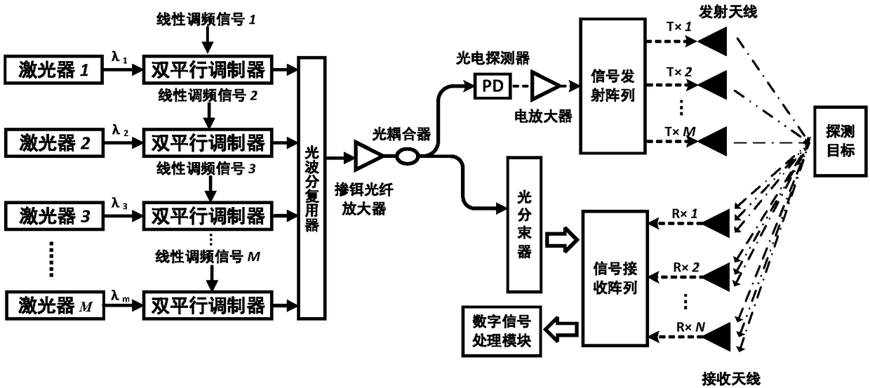
[0041] Aiming at the deficiencies of the existing technologies, the idea of ​​the present invention is to use microwave photon technology combined with a multi-input multi-output radar structure to improve the radar range resolution and azimuth resolution to overcome the problem of limited target detection capabilities of traditional radars.

[0042]Specifically, at the transmitting end, M channels of IF chirp signals with the same bandwidth and chirp rate and non-overlapping frequencies are modulated on M channels of optical carriers with different wavelengths in one-to-one correspondence, and the generated M channels only retain the positive and negative second-order The modulated optical signal of the sideband; the M modulated optical signals are combined by an optical wavelength division multiplexer and divided into two channels; one of them is divided into N beams of reference light; the other optical signal is photoelectrically converted to obtain M Electrical signals of ...


PUM


Abstract

The invention discloses a microwave photon MIMO radar detection method comprising modulating M intermediate-frequency linear frequency-modulated signals with the same bandwidth and chirp rate and non-overlapped frequency on M optical carriers with different wavelengths to generate M optical signals where only the positive and negative second-order sidebands are retained; merging the M optical signals by an optical wavelength division multiplexer and then dividing a combined optical signal into two channels; dividing the optical signal in one channel into N reference light beams; subjecting theoptical signal in the other channel to photoelectric conversion and separating and transmitting M orthogonal linear frequency-modulated signals therein; receiving, by N receiving antennas, the targetreflected signals, performing de-chirp processing and wavelength demultiplexing, and subjecting the obtained M optical signals to photoelectric conversion, low-pass filtering and analog-to-digital conversion to obtain M*N digital signals, processing the digital signals to obtain a target detection result. The invention also discloses a microwave photon MIMO radar system. The method can greatly improve the range resolution and azimuth resolution of the radar system.

Description

technical field [0001] The invention relates to a microwave photon radar detection method, in particular to a microwave photon MIMO (Multiple-Input Multiple-Output, multiple-input multiple-output) radar detection method and a microwave photon MIMO radar system. Background technique [0002] Radar is the main means for humans to detect and identify all-weather targets. Multi-functional, high-precision, and real-time detection has always been the goal pursued by radar researchers. In order to achieve high-performance target detection and high-resolution imaging, large-bandwidth transmitted signals and fast digital signal processing are required to detect objects. Due to the bandwidth limitation of electronic devices, the traditional radar system directly generates only a few gigahertz signals (see [P.Ghelfi, F.Laghezza, F.Scotti, G.Serafino, S.Pinna, D.Onori, E.Lazzeri, and A.Bogoni, "Photonics in radar systems," IEEE Microw.Mag., 16(8), 74-83(2015).]), it is difficult to rea...

Claims


Application Information

Patent Timeline
Patent Type & Authority Applications(China)
IPC IPC(8): G01S17/89
CPCG01S17/89
Inventor 张方正高彬栋潘时龙赵二毛
Owner NANJING UNIV OF AERONAUTICS & ASTRONAUTICS
Why Eureka
Try Eureka