Hydraulic floating power balance brake

A brake and booster technology, applied in the direction of brake types, drum brakes, mechanical equipment, etc., can solve the problems of poor braking performance, braking fading, braking efficiency and heat dissipation of unbalanced brakes, etc., and achieve practical operation Strong performance, improved braking performance, and good stability in use

Pending Publication Date: 2018-07-20
于本林
View PDF0 Cites 0 Cited by
  • Summary
  • Abstract
  • Description
  • Claims
  • Application Information

AI Technical Summary

Problems solved by technology

When the brake drum rotates in the forward direction and reverse direction, there is a brake with a leading shoe and a slave shoe, which is called a leading shoe brake. The leading shoe brake is divided into two types: balanced and unbalanced. When braking The actuating force exerted by the piston is equal, so an additional radial force is generated on the brake drum during the braking process. The brake where the normal force from the two hooves on the brake drum cannot balance each other is called unbalanced. For the brake, there is no direct connection between the leading shoe and the following shoe, and power cannot be transmitted, so additional force cannot be generated; unbalanced brakes have poor braking efficiency and heat dissipation, the braking force of the brake is poor in stability, and the braking force varies greatly , is not easy to control; and due to poor heat dissipation, a large amount of heat will accumulate during the braking process, and the brake pads and drums are prone to extremely complex deformations under the influence of high temperatures, which are prone to brake failure and chattering, causing The braking efficiency decreases, so the braking performance of the unbalanced brake is poor, and it is prone to flicking and deviation during the braking process, which may even lead to safety accidents in severe cases

Method used


Image

  • Hydraulic floating power balance brake
  • Hydraulic floating power balance brake
  • Hydraulic floating power balance brake

Examples


Embodiment 1

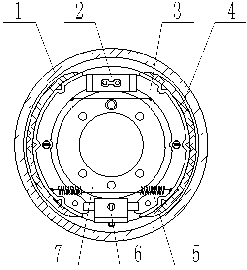
[0052] As shown in the accompanying drawings of the specification, a hydraulic floating booster balance brake includes a brake drum 1, a brake bottom plate 7, a hydraulic cylinder 2 and a brake shoe 3, and the brake drum 1 is provided with a brake shoe 3 and the hydraulic cylinder 2, and the brake shoe 3 is arranged along the inner side of the brake drum 1; the hydraulic cylinder 2 and the brake shoe 3 are both arranged on the brake bottom plate 7, and the brake shoe 3 is provided with a friction plate 4; The booster balance brake is also provided with a booster balance mechanism 6; the booster balance mechanism 6 is symmetrically arranged on the brake base plate 7 with the hydraulic cylinder 2; the brake shoes 3 are provided with two, respectively Arranged on both sides of the brake base plate 7, one end of the two brake shoes is connected with the hydraulic cylinder 2, and the other end is connected with the booster balance mechanism 6, that is, the hydraulic cylinder 3 and t...

Embodiment 2

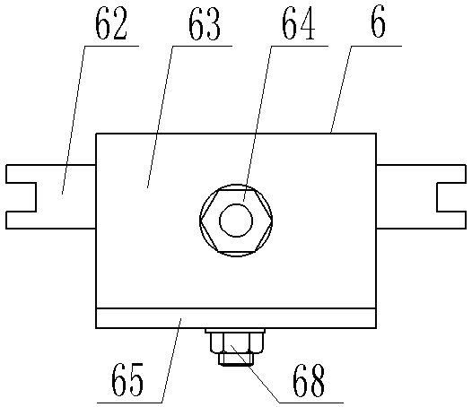
[0055] As shown in the accompanying drawings of the description, based on the hydraulic floating booster balance brake of Embodiment 1, the main board 61 is also provided with a side through hole 611, a groove 1 612, a deep groove 613 and a threaded hole 614; the side through hole 611 It is horizontally arranged in the main board 61 along the opening and closing direction of the brake shoes 3; a connecting mechanism is provided in the side through hole 611 for connecting the main board 61 and the brake shoes 3. The first groove 612, the deep groove 613 and the threaded hole 614 are all designed on the bottom surface of the main board 61; the first groove 612 is arranged in parallel with the deep groove 613, and the deep groove 613 and the threaded hole 614 are on the same horizontal line; The through hole 611 is arranged in parallel above the groove one 612; the top plate mechanism 67 is arranged in the deep groove 613; the spring one 66 is arranged in the groove one 612. The ...

Embodiment 3

[0057] Such as Figure 7 As shown, based on the hydraulic finishing balance brake described in Embodiment 2, a top plate mechanism 67 includes a spring sleeve 671 and a second spring 672; one end of the second spring 672 extends into the deep groove 613 on the main board 61, and the other end Stretch into the spring sleeve 671; the shape and size of the spring sleeve 671 are consistent with the size of the deep groove 613, and the inner diameter of the spring sleeve 671 is equal to the diameter of the spring two 672; In the spherical groove 652 on the plate 65; the spherical surface of the top of the spring sleeve 671 is smaller than the spherical surface of the spherical groove 652.


PUM


Abstract

The invention discloses a hydraulic floating power balance brake. The hydraulic floating power balance brake comprises a brake drum, a brake bottom plate, a hydraulic sub-pump and a brake shoe, wherein the brake shoe and the hydraulic sub-pump are arranged in the brake drum, and the brake shoe is arranged along the inner side of the brake drum; the hydraulic sub-pump and the brake shoe are arranged on the brake bottom plate, and the brake shoe is provided with a friction plate; the hydraulic floating power balance brake further comprises a power balance mechanism, and the power balance mechanism and the hydraulic sub-pump are symmetrically arranged on the brake bottom plate; and one end of the brake shoe is connected with the hydraulic sub-pump, and the other end of the brake shoe is connected with the power balance mechanism. Through design of the power balance mechanism and combination of the power balance mechanism with hydraulic power transmission advantages, hydraulic power balance braking is achieved, the braking performance of the vehicle brake is greatly improved, the application range of the hydraulic brake is extended, and the hydraulic floating power balance brake is simple in structure, economical, practical and high in application and popularization value.

Description

technical field [0001] The invention relates to the technical field of automobile braking, in particular to a hydraulic floating booster balance brake used on small and medium-sized vehicles. Background technique [0002] At present, in the field of brake technology, automotive brakes can be divided into two categories: industrial brakes and automotive brakes, and automotive brakes are further divided into service brakes and parking brakes. The resistance torque that must be applied in the brake to stop or decelerate the mechanical moving parts is called the braking torque. Braking torque is the basis for designing and selecting brakes, and its size is determined by the type of machinery and work requirements. The performance of the brake parts used on the brake directly affects the braking process, and the main factors affecting its performance are the working temperature and the temperature rise rate. [0003] The earliest designed drum brake system in automobile braking...

Claims


Application Information

Patent Timeline
Patent Type & Authority Applications(China)
IPC IPC(8): F16D51/00
CPCF16D51/00F16D2051/001
Inventor 于本林
Owner 于本林
Why Eureka
Try Eureka