Joint Replacement Prosthesis

A joint replacement and prosthesis technology, applied in the direction of prosthesis, joint implants, joint implants, etc., can solve the problem of weak coating, failure of implanted prosthesis without consideration of peeling of the layer from the polymer substrate, Implanted prosthesis and bone tissue are not firmly connected to achieve the effect of avoiding fluid accumulation and inflammation, light weight, and improving the degree of integration

Active Publication Date: 2020-05-19
刘洋
View PDF12 Cites 0 Cited by
  • Summary
  • Abstract
  • Description
  • Claims
  • Application Information

AI Technical Summary

Problems solved by technology

However, there are two problems with this prosthesis: one is how to achieve a firm combination of the multi-layer structure. This prior art does not disclose how the non-degradable metal layer is formed, nor does it consider the implantation caused by the peeling of the layer from the polymer substrate. In order to solve the problem of failure of implant prosthesis, its outer layer is realized by spraying magnesium or magnesium alloy. If it is sintered and solidified, its polymer matrix cannot withstand the high temperature. If it is only simply coated, there must be a problem that the coating is not firm; the second is The growth of bone cells on the surface of the implanted prosthesis is not achieved overnight and uniformly synchronized. The surface of the prior art is smooth and does not provide initial attachment sites for bone cells, and the degradable metal coating is corroded and damaged. In the process of exposing the non-degradable metal layer, the coating to which bone cells adhere is continuously degraded, resulting in a substantially weak connection between the implanted prosthesis and the bone tissue

Method used


Image

  • Joint Replacement Prosthesis
  • Joint Replacement Prosthesis
  • Joint Replacement Prosthesis

Examples


Embodiment 1

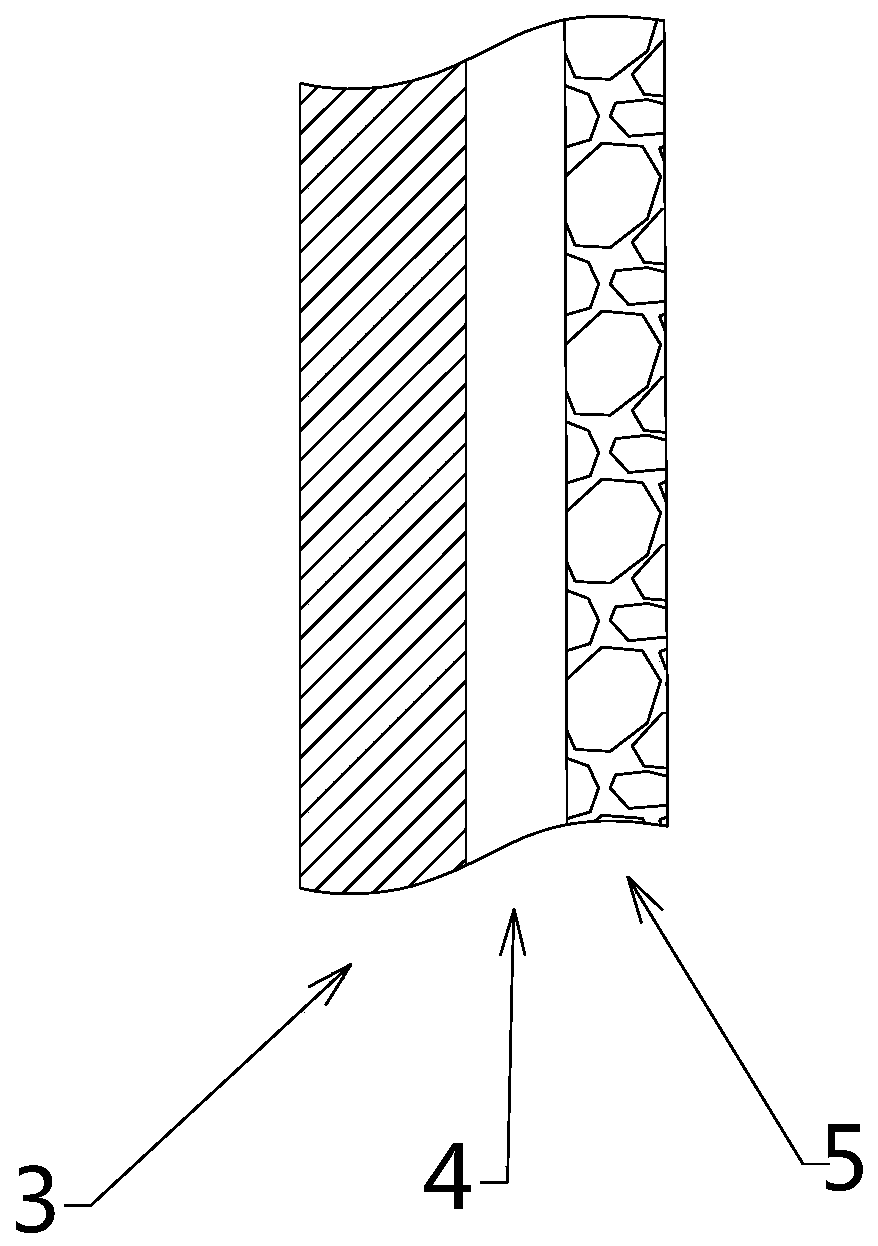
[0030] This embodiment shows the joint replacement prosthesis with non-degradable metal layer 3 and degradable metal layer 4 and its preparation method.

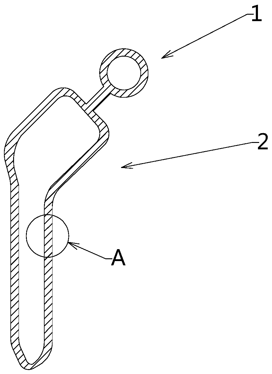
[0031] see figure 1 , the joint replacement prosthesis has a prosthesis head 1 and a prosthesis lower part 2 connected as one, the prosthesis head 1 is in the natural shape of a bone end, the prosthesis lower part 2 is rod-shaped, and the prosthesis Both the body head 1 and the lower part of the prosthesis 2 are hollow structures made of non-degradable polymer material 3 . The hollow structure made of the non-reducible polymer material 3 uses polyether ether ketone as the manufacturing material, and is formed by injecting molten polyether ether ketone into a mold of a corresponding shape using a single-screw extruder to obtain a joint replacement prosthesis polymer matrix. The inner wall of the mold has protrusions with a height ranging from 100-120 μm, so that the surface of the polymer matrix has corresponding blind hole...

Embodiment 2

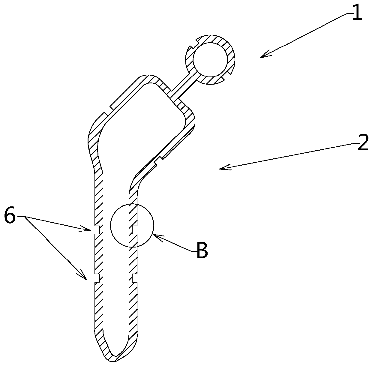
[0035] This example shows a joint replacement prosthesis with a groove 5 filled with a degradable polymer.

[0036] see image 3, using high-density polyethylene as raw material, according to the actual situation of the patient's defective bone restored from the CT image, the hollow matrix with the groove 5 is manufactured by 3D printing. The groove 5 surrounds the prosthesis for one week, with a width of 0.4 mm and a depth of 0.25 mm.

[0037] see Figure 4 , dipping the matrix into the gel of polylactic acid, and stirring the matrix in the gel so that the polylactic acid remains in the groove 5, taking out the matrix and wiping to remove more polylactic acid attached to the surface of the body.

[0038] Subsequently, the groove 5 with polylactic acid was covered with a removable adhesive tape, and then a titanium-zirconium alloy layer with a thickness of 40 μm was covered by physical vapor deposition as the non-degradable metal layer 3 . Referring again to the method show...


PUM


Abstract

The invention relates to the field of medical apparatuses and instruments, in particular to a joint replacement prosthesis. The joint replacement prosthesis comprises a prosthesis head part and a prosthesis lower part which are integrally formed, wherein the prosthesis head part is in an epiphysis shape, the prosthesis lower part is in a rod shape, both the prosthesis head part and the prosthesislower part are hollow structures made from non-degradable polymer materials, and the surface of the joint replacement prosthesis is sequentially covered with a non-degradable metal layer and a degradable metal layer. The joint replacement prosthesis is characterized in that the non-degradable metal layer is formed through physical vapor deposition or chemical vapor deposition. The joint replacement prosthesis meets the light-weight corrosion-resistant basic requirements, and also has the good osteocyte attachment capacity, and good combination between the joint replacement prosthesis and bonetissue can be achieved in short time when the prosthesis is implanted.

Description

technical field [0001] The invention relates to the field of medical devices, in particular to a prosthesis for joint replacement. Background technique [0002] Artificial joint replacement is a relatively mature medical technology at present. After years of theoretical development and clinical practice, the operation of joint replacement is becoming more and more mature. The success of artificial joint replacement, especially postoperative healing and functional recovery, is increasingly limited by the development of replacement prostheses. [0003] Early replacement prostheses were mainly made of stainless steel or titanium alloy, and their large weight affected the functional recovery of patients after surgery. The prior art (CN205107980U) discloses a bionic joint replacement prosthesis with a hollow structure, long grooves and through holes, which can reduce the weight of the prosthesis and promote the integration of the prosthesis and bone tissue. However, the bionic ...

Claims


Application Information

Patent Timeline
Patent Type & Authority Patents(China)
IPC IPC(8): A61F2/30
CPCA61F2/30767A61F2002/3006A61F2002/30827A61F2002/30929A61F2002/3093
Inventor 刘洋
Owner 刘洋
Why Eureka
Try Eureka