A kind of vena cava retrograde perfusion tube and using method thereof

A vena cava and perfusion tube technology, applied in the field of medical devices, can solve the problem of inability to implement selective cerebral perfusion combined with inferior vena cava retrograde perfusion, and achieve the effects of simple structure, short preparation time and fast conversion

Active Publication Date: 2020-07-17
WEST CHINA HOSPITAL SICHUAN UNIV
View PDF6 Cites 0 Cited by
  • Summary
  • Abstract
  • Description
  • Claims
  • Application Information

AI Technical Summary

Problems solved by technology

[0005] However, the existing extracorporeal circulation devices can only implement selective cerebral perfusion (ACP+DHCA) under deep hypothermic circulatory arrest, and cannot implement selective cerebral perfusion combined with retrograde vena cava perfusion (ACP+RIVP). There is an urgent need for a product that can be directly used for ACP +RIVP

Method used


Image

  • A kind of vena cava retrograde perfusion tube and using method thereof
  • A kind of vena cava retrograde perfusion tube and using method thereof
  • A kind of vena cava retrograde perfusion tube and using method thereof

Examples


Embodiment 1

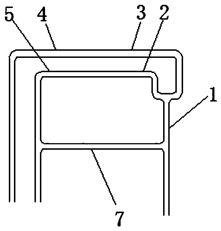
[0039] like figure 1 As shown, a retrograde vena cava perfusion tube includes an arterial perfusion tube 1, one end of the arterial perfusion tube 1 is connected with an arterial perfusion branch pipe A2 and an arterial perfusion branch pipe B3, the free end of the arterial perfusion branch pipe A2 is connected with one end of the vena cava drainage tube A5, and the arterial perfusion branch pipe A2 is connected to one end of the vena cava drainage tube A5. The free end of the perfusion branch tube B3 is connected to one end of the vena cava drainage tube B4, the arterial perfusion branch tube A2 and the vena cava drainage tube A5, the arterial perfusion branch tube B3 and the vena cava drainage tube B4 are integrally formed, and the vena cava drainage tube B4 or the vena cava drainage tube B4 are integrally formed. The venous drainage tube A5 is connected to the arterial perfusion tube 1 through the retrograde perfusion tube 7. In this embodiment, the vena cava drainage tube A...

Embodiment 2

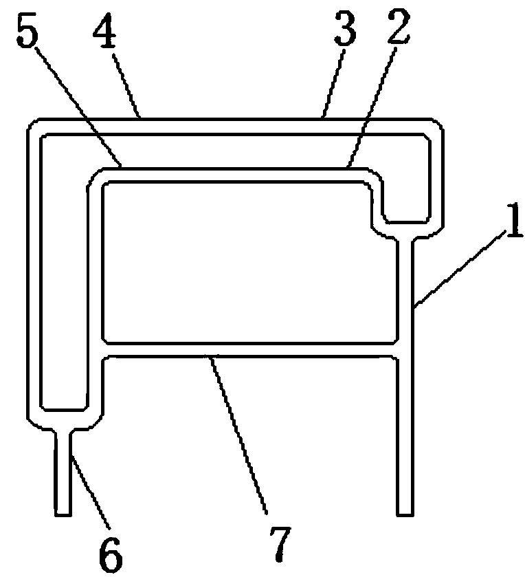
[0048] The difference from Embodiment 1 is that: the free end of the vena cava drainage tube A5 and the free end of the vena cava drainage tube B4 are connected to one end of the main venous blood return main pipe 6, and the main venous blood return main pipe 6 is a flexible pipe. like figure 2 shown.

[0049] The method for using the retrograde vena cava perfusion tube comprises the following steps:

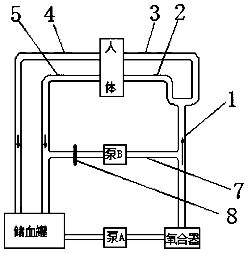
[0050] Step 1. Connect the arterial perfusion tube 1 to the outlet of the oxygenator, connect the venous return main tube 6 to the blood storage tank, set the pump A between the blood storage tank and the inlet of the oxygenator, and connect the retrograde perfusion tube 7 to the blood storage tank. Set pump B on;

[0051] Step 2, under the drive of pump A and pump B, fill the entire perfusion system with sterile liquid;

[0052] Step 3. Cut out the arterial perfusion branch tube A2 and the vena cava drainage tube A5, the arterial perfusion branch tube B3 and the vena cava dra...


PUM


Abstract

The invention discloses a vena cava retroperfusion tube and a use method thereof, and belongs to the field of medical apparatuses. The vena cava retroperfusion tube comprises an arterial perfusion tube. The arterial perfusion tube is connected with an arterial perfusion branch tube A and an arterial perfusion branch tube B. The free end of the arterial perfusion branch tube A is connected with oneend of a vena cava drainage tube A. The free end of the arterial perfusion branch tube B is connected with one end of a vena cava drainage tube B. The arterial perfusion branch tube A and the vena cava drainage tube A are integrally formed, and the arterial perfusion branch tube B and the vena cava drainage tube B are integrally formed. The vena cava drainage tube A or the vena cava drainage tubeB is connected with the arterial perfusion tube through a retroperfusion tube body. The arterial perfusion branch tube A, the arterial perfusion branch tube B, vena cava drainage tube A and the venacava drainage tube B are all hoses. The vena cava retroperfusion tube has the advantages of being convenient to operate, short in preparing time and capable of being rapidly switched among various perfusion modes.

Description

technical field [0001] The invention relates to the field of medical devices, in particular to a vena cava retrograde perfusion tube and a method for using the same. Background technique [0002] Extracorporeal circulation refers to the technology of using a special device to temporarily replace the human heart and lungs for blood circulation and gas exchange. This device is divided into artificial heart (pump) and artificial lung (oxygenator), also collectively referred to as artificial heart and lung, artificial heart and lung device or extracorporeal circulation device. During extracorporeal circulation, the venous blood is introduced into the blood storage tank through the superior vena cava cannula and the inferior vena cava cannula. The artificial heart (pump) pumps the venous blood into the artificial lung for oxygenation and discharges carbon dioxide. The oxygenated blood is maintained by the artificial heart. A certain pressure is pumped into the arterial system in...

Claims


Application Information

Patent Timeline
Patent Type & Authority Patents(China)
IPC IPC(8): A61M1/36
CPCA61M1/3621A61M1/3653
Inventor 熊际月谭赵霞罗明杜磊
Owner WEST CHINA HOSPITAL SICHUAN UNIV
Why Eureka
Try Eureka