
Vehicle-mounted multiplex charging machine

A charger and vehicle-mounted technology, applied in electric vehicle charging technology, charging stations, electric vehicles, etc., can solve the problems such as the inability to flexibly implement charging voltage follow-up and charging current follow-up, the inability to realize two-way flow of electric energy, and the inability to share hardware circuits. , to achieve the effect of improving flexibility, high integration and multiplexing, and realizing charging voltage follow-up and charging current follow-up control

Active Publication Date: 2018-07-24
HEFEI JUYI POWER SYST CO LTD
View PDF9 Cites 13 Cited by
  • Summary
  • Abstract
  • Description
  • Claims
  • Application Information

AI Technical Summary

Problems solved by technology

[0005] (1) More power devices are used, which increases the hardware cost;
[0006] (2) The power can only be transmitted from the grid to the car battery, and the two-way flow of electric energy cannot be realized;
[0007] (3) The charging voltage follow and charge current follow cannot be flexibly realized;
[0008] (4) The degree of reuse is low, and hardware circuits cannot be shared with other automotive electronic devices

Method used


Image

  • Vehicle-mounted multiplex charging machine
  • Vehicle-mounted multiplex charging machine
  • Vehicle-mounted multiplex charging machine

Examples


Embodiment 1

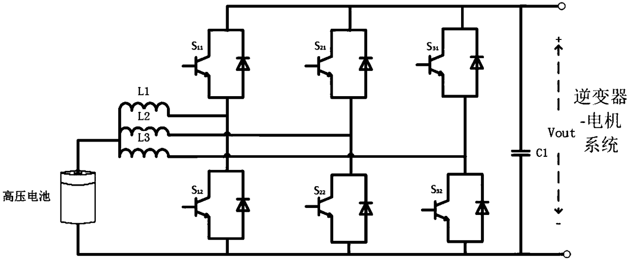
[0048] Boost working state: When the device works in the Boost boost circuit, the relay switches S1, S2, and S3 are closed; the grid connector 1 and grid connector 2 are suspended, and the inverter-motor system is working and the car is working in the driving state. When the system works in the Boost boost circuit, the equivalent circuit is as follows figure 2 Shown:

[0049] At this time, the high-voltage battery voltage Vg passes through a multiple multi-phase Boost circuit composed of inductors, three-phase IGBT bridge arms and output capacitor filters. According to the duty cycle D (0<D<1), the pump rises to Vg / (1-D) and remain stable.

Embodiment 2

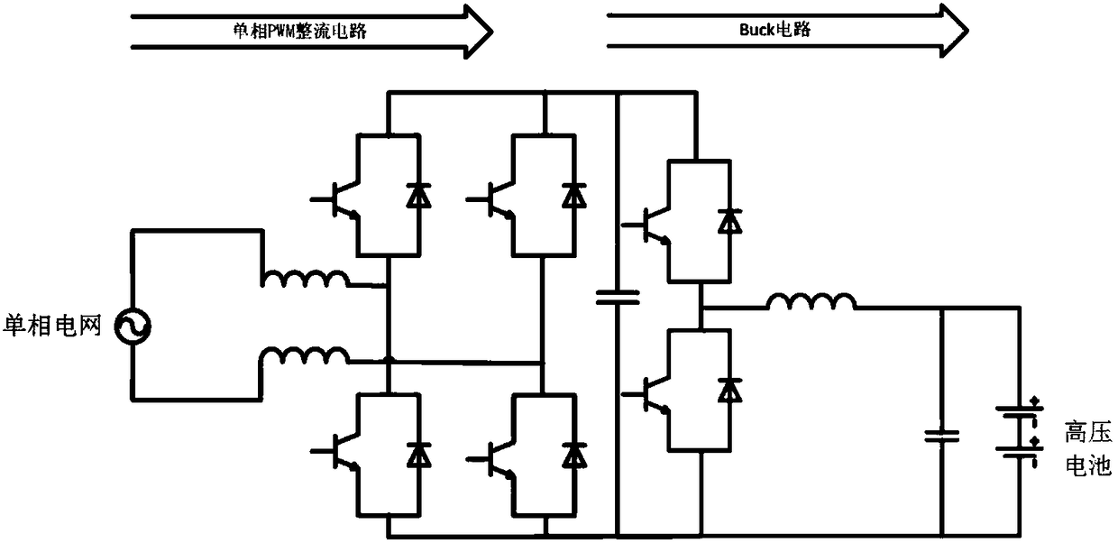
[0051]Single-phase grid connected to battery charging state: when the device is working in single-phase rectification charging state, relay switches S1 and S2 are disconnected, and relay switch S3 is closed; grid connector 1 and grid connector 2 are connected to single-phase grid (neutral line and live wire), the car does not run. The system works in the state of single-phase rectification and charging, and the grid energy is transferred to the battery through the single-phase PWM rectification circuit and Buck power factor correction circuit to charge the battery. Equivalent circuit such as image 3 Shown:

[0052] At this time, bridge arms 1 and 2 form a PWM rectifier circuit, and the rectifier circuit works in a bipolar modulation state. The power frequency grid voltage is rectified into a higher DC high voltage, and then through the Buck circuit, the battery is charged through the voltage following or current following control mode.

[0053] What is going to be explaine...

Embodiment 3

[0059] Single-phase grid-connected inverter state: When single-phase grid-connected inverter, the system connection method is the same as that of single-phase PWM rectification and rectification circuit, sharing the same set of equipment, but the direction of energy flow is opposite to that of single-phase rectification and charging. When the active or reactive power of the grid is insufficient, the new energy vehicle equipped with the invention can be used to balance the load of the grid.


PUM


Abstract

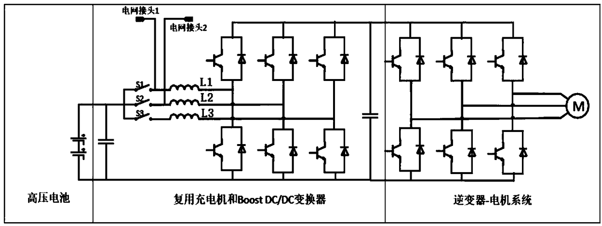
The invention discloses a vehicle-mounted multiplex charging machine. The vehicle-mounted multiplex charging machine comprises a high-voltage battery, three inductors L1, L2 and L3, and three IGBT bridge arms in parallel connection mutually. A positive pole of the high-voltage battery is connected with one ends of the inductors L1, L2 and L3 through relay switches S1, S2 and S3. The other ends ofthe inductors L1, L2 and L3 are connected with middle nodes of the three IGBT bridge arms correspondingly. A negative pole of the high-voltage battery is directly connected with a jointly-connecting end of the three IGBT bridge arms. The connecting ends of the relay switches S1 and S2 and the inductors L1 and L2 are a live line connector and a zero line connector of a power grid correspondingly. The two ends of the three IGBT bridge arms in parallel connection mutually are connected with an inverter-motor system. IGBT devices constituting the three IGBT bridge arms are connected and controlledthrough a controller module. When the vehicle-mounted multiplex charging machine works, a Boost working state, a state of single-phase power grid connection to charge the battery, a single-phase grid-connected inversion state, and a vehicle-vehicle mutually-charging state are included. The vehicle-mounted multiplex charging machine adopts different relay switch combinations, equipment can work indifferent states, and different functions are achieved.

Description

technical field [0001] The invention relates to new energy vehicle charging technology, in particular to a vehicle-mounted multiplexing charger. Background technique [0002] The existing vehicle-mounted multiplexing charging technology for new energy vehicles generally adopts a single-phase grid voltage input + uncontrolled rectification circuit + PFC power factor correction circuit + high-frequency isolation circuit + filter circuit scheme. [0003] Patent Publication 1 "Charging and Discharging Control System for Electric Vehicles and Electric Vehicles" (publication number: CN 202455130U) proposes a solution for charging batteries by combining a motor inverter and a single-phase Boost circuit; 2 "Electric Vehicles and Vehicle Chargers for Electric Vehicles" (publication number: CN 204835609 U) proposes a device that can charge high-voltage and low-voltage batteries on vehicles; patent publication 3 "Electric Vehicles, Vehicle Chargers and its overcurrent protection circu...

Claims


Application Information

Patent Timeline
Patent Type & Authority Applications(China)
IPC IPC(8): B60L11/18H02J3/32
CPCB60L53/20B60L53/24B60L2210/10B60L2210/30H02J3/32Y02T10/70Y02T10/7072Y02T10/72Y02T90/14
Inventor 刘蕾郭梓暄班建安范佳伦张茨
Owner HEFEI JUYI POWER SYST CO LTD
Learn More