
High vacuum winding type capacitor coating machine

A winding-type coating machine technology, which is applied in the field of coating machines, can solve the problems of affecting normal use, poor adhesion of the base film, inconvenient adjustment of the pressure of the base film, etc., and achieves the effect of strong practicability and improved adhesion

Inactive Publication Date: 2018-07-24
广州市邦图机电科技有限公司
View PDF4 Cites 3 Cited by
  • Summary
  • Abstract
  • Description
  • Claims
  • Application Information

AI Technical Summary

Problems solved by technology

[0003] The structure of the coating machine in the prior art is relatively simple, and it is subject to certain limitations in the process of use. It is inconvenient to adjust the pressure of the base film on the surface of the coating drum, and at the same time affects the relationship between the cooled coating drum and the coated base film. The heat conduction efficiency, the temperature between the base film and the plating drum, and the line speed are inconvenient to change, and the adhesion of the base film to the plating drum is poor, which affects normal use

Method used


Image

  • High vacuum winding type capacitor coating machine
  • High vacuum winding type capacitor coating machine
  • High vacuum winding type capacitor coating machine

Examples


Embodiment 1

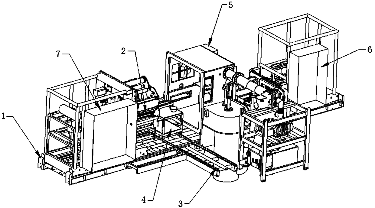
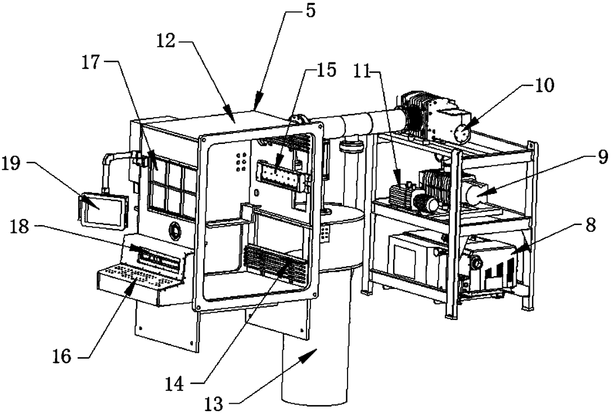
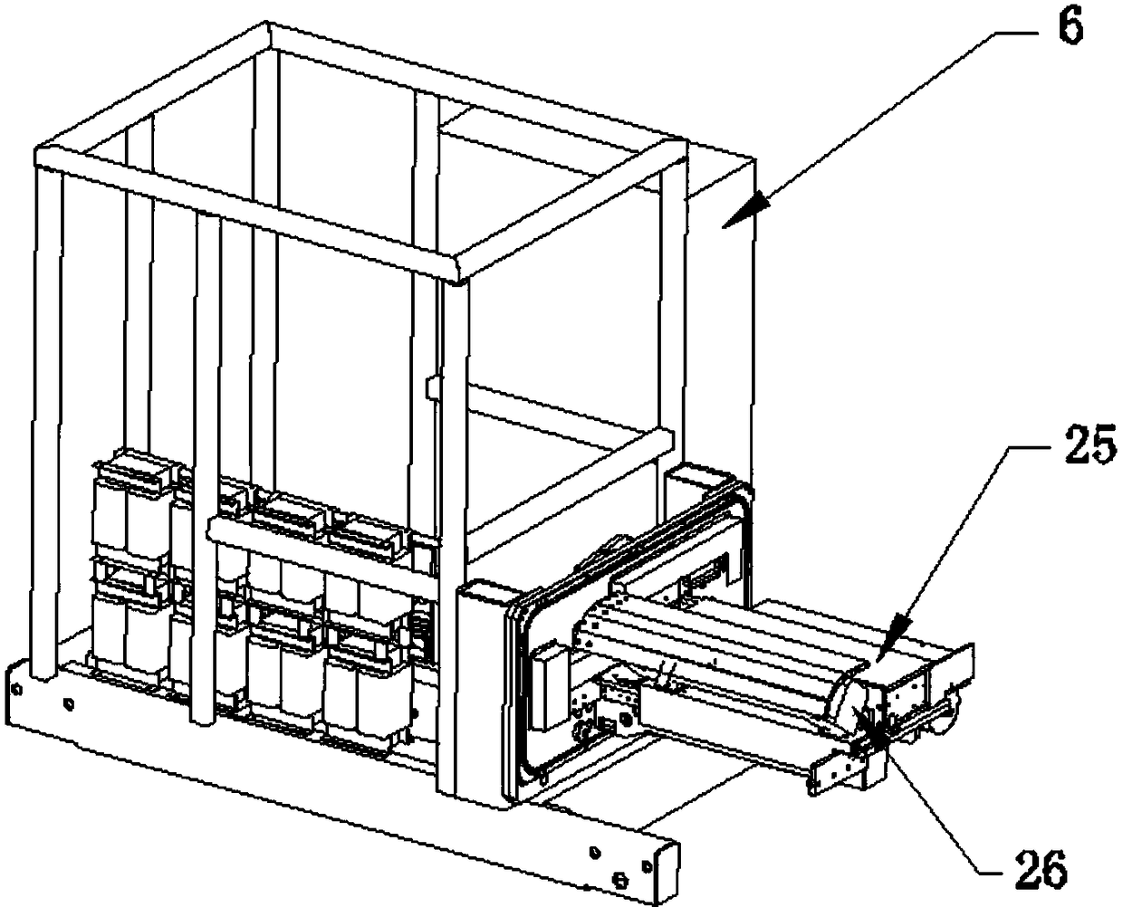
[0024] Such as Figure 1-4 As shown, the present invention provides a high-vacuum winding-type capacitor coating machine, comprising a main rail 1 of the equipment, the top of the main rail 1 of the equipment is equipped with a coiling system electric cabinet 7, and one side of the coiling system electric cabinet 7 is provided with an oil Evaporation system 2, one side of the oil evaporation system 2 is provided with a service cart 4, the bottom of the service cart 4 is provided with a service cart guide rail 3, one side of the service cart 4 is provided with a vacuum system electric cabinet 5, the vacuum system electric cabinet 5 An evaporation system electrical cabinet 6 is arranged on one side, and a diffusion pump 13 is installed at the bottom of the vacuum system electrical cabinet 5. A vacuum chamber 12 is installed on the top side of the diffusion pump 13, and a cold well is installed on the inner bottom side of the vacuum chamber 12. Steel pipe 14, the top of the cold ...


PUM


Abstract

The invention discloses a high vacuum winding type capacitor coating machine, comprising an equipment main guide rail; a roll burning system electric cabinet is installed at the top end of the equipment main guide rail; an oil evaporation system is arranged at one side of the roll burning system electric cabinet; a service trolley is arranged at one side of the oil evaporation system, a service trolley guide rail is arranged at the bottom end of the service trolley, and a vacuum system electric cabinet is arranged at one side of the service trolley; an evaporation system electric cabinet is arranged at one side of the vacuum system electric cabinet; a diffusion pump is arranged at the bottom end of the vacuum system electric cabinet; a vacuum chamber is installed at one side of the top endof the diffusion pump, a cold well steel pipe is arranged at one side of the bottom end in the vacuum chamber, and a pretreatment system is arranged at the top end of the cold well steel pipe; a front window is arranged at one side of the vacuum chamber. According to the high vacuum winding type capacitor coating machine, a tension roller is arranged for controlling the pressure of a base film onthe surface of a plating drum, the planting drum is arranged for driving the base film to pass through the evaporation system, and heat received by the base film due to the vapor deposition is takenaway by means of a temperature system connected with the plating drum, so that the adhesion of the base film on the plating drum can be improved.

Description

technical field [0001] The invention relates to a coating machine, in particular to a high-vacuum winding capacitor coating machine. Background technique [0002] As we all know, a vacuum coating machine mainly refers to a type of coating that needs to be carried out under a relatively high vacuum, including many types, including vacuum ion evaporation, magnetron sputtering, MBE molecular beam epitaxy, PLD laser sputtering deposition, etc., mainly It is divided into two types: evaporation and sputtering. The substrate that needs to be coated is called the substrate, and the material to be coated is called the target. The substrate and the target are in the same vacuum chamber. Evaporation coating is generally heated to make the surface components Atom groups or ions are evaporated and deposited on the surface of the substrate to form a film through the film formation process (scattered-island structure-vagus structure-layered growth). For sputtering coatings, it can be simpl...

Claims


Application Information

Patent Timeline
Patent Type & Authority Applications(China)
IPC IPC(8): C23C14/56C23C14/24
Inventor 包中敢
Owner 广州市邦图机电科技有限公司
Learn More