Thermal insulation wallboard and thermal-bridge-free connecting manner thereof

A technology of thermal insulation wall panels and connection methods, applied in thermal insulation, walls, building components, etc., can solve the problems that the thermal insulation effect cannot be kept in a good state for a long time, the living comfort is reduced, and the thermal insulation ability is weakened, so as to improve the energy saving and thermal insulation effect, The effect of improving the seismic performance of the structure and reducing the self-weight

Inactive Publication Date: 2018-07-24
SHENYANG JIANZHU UNIVERSITY
0 Cites 0 Cited by

AI-Extracted Technical Summary

Problems solved by technology

In terms of building energy consumption, the energy consumption caused by exterior walls accounts for more than 50% of the total building energy consumption. Therefore, wall insulation is the key to achieving building energy conservation. The environmental hazards of clay brick production are well known. It consumes a lot of energy, and the exhaust gas produced causes air pollution, greenhouse effect...

Abstract

The invention provides a thermal insulation wallboard and a thermal-bridge-free connecting manner thereof, belongs to the technical field of buildings, and has the beneficial effects of simple structure, reasonable design and low steel consumption. Aerated concrete is adopted to reduce the self-weight of the wallboard, increase the ductility and energy-dissipating capacity of the structure, and further improve the anti-seismic property of the structure; a connector is adopted for connecting at a joint of the wallboards; an anchoring frame and a connecting rod are used for connecting light connecting steel plates to realize primary fixed connection; a hooping connecting piece is arranged for anchoring connecting longitudinal bars, secondary anchoring connection is performed to improve the strength and stability of the wallboard connection; through adopting a resin glue adhesive, protruded interfaces and recessed interfaces can be tightly engaged, all horizontal and vertical joints at the joint of the wallboards are staggered, the thermal bridge effect at the positions such as the connection joints can be avoided without adopting other thermal insulation manners, the energy-saving and thermal insulation effects of the wallboard are improved, the thermal bridge in the wallboard can be eliminated while the connection strength of the wallboard is ensured, and the energy consumptionis reduced.

Application Domain

WallsHeat proofing

Technology Topic

Steel platesDuctility +8

Image

  • Thermal insulation wallboard and thermal-bridge-free connecting manner thereof
  • Thermal insulation wallboard and thermal-bridge-free connecting manner thereof
  • Thermal insulation wallboard and thermal-bridge-free connecting manner thereof

Examples

  • Experimental program(1)

Example Embodiment

[0020] In order to further illustrate the present invention, the following describes the present invention in detail with reference to the accompanying drawings and embodiments, but they should not be understood as limiting the protection scope of the present invention.
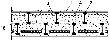
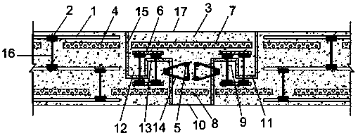
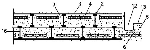
[0021] Such as Figure 1~5 As shown, in the thermal insulation wallboard and its non-thermal bridge connection method, three layers of lightweight metal plates (1) are arranged in the aerated concrete (3), and the aerated concrete (3) is placed between the lightweight metal plates (1). ) Are provided with two rows of sandwich insulation boards (4), the sandwich insulation boards (4) are arranged in two rows in the aerated concrete (3) at intervals, and the sandwich insulation boards (4) between the same rows are arranged at equal intervals , The spacing is set at 250~400mm, the sandwich insulation boards (4) between different rows are staggered to each other, and the adjacent lightweight metal plates (1) are fixedly connected by anchor frames (2) and connecting rods (16); The anchor frames (2) and connecting rods (16) in the same row are arranged at equal intervals on the lightweight metal plate (1). The height of the connecting rods (16) is one third of the thickness of the aerated concrete (3). An anchor frame (2) is set at the connection between the connecting rod (16) and the light metal plate (1); the two wall panels to be connected are connected by a connector (17), and the two wall panels are connected at the connection point There are connecting longitudinal ribs (5), lightweight connecting steel plates (6), body recessed interfaces (12) and body protruding interfaces (13); the connecting body (17) is filled with aerated concrete (3) and is provided with a connection Longitudinal rib (5), lightweight connecting steel plate (6), non-interface side sandwich insulation board (7), protruding large interface sandwich insulation board (8), recessed interface (9), large protruding interface (10) and Small protrusion interface (11), the protrusion height of the small protrusion interface (11) is smaller than the recess depth of the body recessed interface (12), and the protrusion height of the body protrusion interface (13) is smaller than the recess of the recess interface (9) Depth, so that a bonding space for filling the resin glue adhesive (15) is formed between the connection of the two wall panels to be connected and the connecting body (17); the light weight is set at the connection of the two wall panels to be connected The connecting steel plate (6) and the lightweight connecting steel plate (6) set in the connecting body (17) are initially fixedly connected by the anchor frame (2) and the connecting rod (16), and are set at the connection of the two wall panels to be connected The connecting longitudinal ribs (5) and the connecting longitudinal ribs (5) provided in the connecting body (17) are again anchored and connected by the stirrup connector (14), which improves the anchoring effect and improves the strength and stability of the wallboard connection; The light metal plate (1) is made of a low yield point steel plate; the light connecting steel plate (6) is made of a higher yield point steel plate; the sandwich insulation board (4), non-interface side clamps The core insulation board (7) and the protruding large interface sandwich insulation board (8) adopt polystyrene board or rigid polyurethane foam board; the stirrup connectors (14) are arranged at equal intervals along the height direction of the wallboard, and the vertical direction The distance between the upper adjacent stirrup connecting pieces (14) is set at 180~200mm; the connecting longitudinal ribs (5) and the stirrup connecting pieces (14) are connected by welding and ensure sufficient anchoring; the connecting longitudinal ribs (5) ), stirrup connecting piece (14) and connecting rod (16) adopt galvanized anti-corrosion treatment.
[0022] The above are only the preferred embodiments of the present invention. It should be pointed out that for those of ordinary skill in the art, without departing from the principle of the present invention, several improvements and modifications can be made, and these improvements and modifications are also It should be regarded as the protection scope of the present invention.

PUM

no PUM

Description & Claims & Application Information

We can also present the details of the Description, Claims and Application information to help users get a comprehensive understanding of the technical details of the patent, such as background art, summary of invention, brief description of drawings, description of embodiments, and other original content. On the other hand, users can also determine the specific scope of protection of the technology through the list of claims; as well as understand the changes in the life cycle of the technology with the presentation of the patent timeline. Login to view more.

Similar technology patents

Photoelectric sensor for position of sun

InactiveCN101650173AEffective tracking range expandedSimple structure
Owner:WUHAN UNIV OF TECH

Magnetic cooling apparatus and control method thereof

ActiveUS20130180263A1simple structure
Owner:SAMSUNG ELECTRONICS CO LTD

Dual-Drivetrain of Power-Assist Vehicle

InactiveUS20100181130A1enhance uphill momentumsimple structure
Owner:CHOU WEN CHENG

Classification and recommendation of technical efficacy words

  • Simple structure
  • reasonable design

Method for coal and gas outburst simulation experiment

Owner:CHINA COAL TECH ENG GRP CHONGQING RES INST

Embedding accuracy control construction method for embedded part of overlong equipment foundation platform

InactiveCN102134879Areasonable designSimple construction steps
Owner:SCEGC NO 6 CONSTR ENG GRP CO LTD

Frequency hopping communication anti-interference method based on cognitive radio

ActiveCN103441779AImprove anti-jamming communication abilityreasonable design
Owner:深圳市研谱科技有限公司
Why Eureka
Try Eureka