Novel by-stage construction carbon fiber confined concrete laminated column

A technology for confining concrete and carbon fiber, applied in the direction of columns, piers, pillars, etc., can solve the problem that the superiority of superimposed secondary force cannot be exerted, the bearing capacity and ductility of components, energy dissipation capacity, and the inability to effectively constrain core concrete, etc. problem, to achieve the effect of simple structure, improved seismic performance and high strength

Inactive Publication Date: 2018-07-24
HUNAN UNIV
View PDF3 Cites 3 Cited by
  • Summary
  • Abstract
  • Description
  • Claims
  • Application Information

AI Technical Summary

Problems solved by technology

However, because the steel pipe cooperates with the concrete to bear the force together, the steel pipe is in a complex stress state of partial tension and partial compression under strong earthquakes, which will cause the steel pipe to be unable to effectively restrain the core concrete, so the superiority of the superimposed secondary stress cannot be exerted. At the same time, it will reduce the bearing capacity, ductility and energy dissipation capacity of the component

Method used


Image

  • Novel by-stage construction carbon fiber confined concrete laminated column
  • Novel by-stage construction carbon fiber confined concrete laminated column
  • Novel by-stage construction carbon fiber confined concrete laminated column

Examples


Embodiment Construction

[0025] Preferred examples of the present invention will be described below with reference to the accompanying drawings.

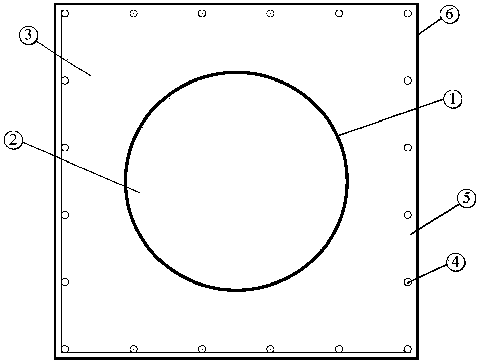
[0026] see figure 1 As shown, the embodiment of the present invention provides a carbon fiber-confined concrete composite column, and the carbon fiber-confined concrete composite column includes: internal carbon fiber cloth (1), core concrete (2), peripheral concrete (3), longitudinal reinforcement ( 4), stirrups (5) and outer carbon fiber cloth (6) in the bottom area.

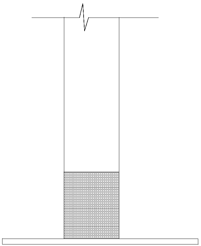
[0027] The outer cladding of the core carbon fiber confined concrete column composed of (1), (2) is provided with the reinforced concrete part composed of (3), (4), (5), and the (3), (4), (5 ) The bottom area of ​​the reinforced concrete part composed of a certain height of carbon fiber cloth is set to form a restraint effect on the plastic hinge area.

[0028] Preferably, the cross-section of the core carbon fiber-confined concrete column is circular.

[0029] Preferably, the cross-sect...


PUM


Abstract

The invention discloses a by-stage construction carbon fiber confined concrete laminated column. The by-stage construction carbon fiber confined concrete laminated column is the combination of internal carbon fiber and core concrete, and the combination of carbon fiber in a bottom area and peripheral reinforced concrete, and is a multi-combination confined carbon fiber concrete laminated column. External carbon fiber cloth in the bottom area facilitates improving of horizontal resistance, ductility and the energy dissipation ability of the laminated column; due to the fact that column damage generally occurs at the reinforced concrete part on the periphery of the bottom, through strengthening of the bottom, the cross section area of the laminated column can be effectively decreased, the building using area is increased, and the self-weight is reduced. As for the by-stage construction carbon fiber confined concrete laminated column, the core concrete and internal carbon fiber cloth areconstructed first to bear first-stage axial force, after a certain number of floors is constructed, and the peripheral reinforced concrete part and the carbon fiber cloth at the bottom area are constructed to form the carbon fiber confined concrete laminated column to together bear the horizontal load effect and second-stage axial force; and the by-stage construction carbon fiber confined concretelaminated column can well solve the problem that the column-shaft compression ratio of several floors at the bottom of a high-rise building structure exceeds the limit.

Description

technical field [0001] The invention relates to the field of structural engineering, in particular to a carbon fiber confined concrete composite column. Background technique [0002] The existing phased construction of concrete-filled steel tube composite columns effectively utilizes the relatively large axial bearing capacity of the core steel tube-confined concrete. The outer reinforced concrete part mainly bears the bending moment, and has the characteristics of high load-bearing capacity, good ductility, and excellent blast and impact resistance. However, because the steel pipe cooperates with the concrete to bear the force together, the steel pipe is in a complex stress state of partial tension and partial compression under strong earthquakes, which will cause the steel pipe to be unable to effectively restrain the core concrete, so the superiority of the superimposed secondary stress cannot be exerted. At the same time, the bearing capacity, ductility and energy dissi...

Claims


Application Information

Patent Timeline
Patent Type & Authority Applications(China)
IPC IPC(8): E04C3/34
CPCE04C3/34
Inventor 黄远黄登杨扬
Owner HUNAN UNIV
Why Eureka
Try Eureka