
Cervical biopsy area identification method and device based on channel information multimodal network

A region recognition, multimodal technology, applied in the field of medical image processing, can solve the problems of inconsistent common medical methods and the inability of doctors to make more accurate judgments, and achieve the effect of accurate recognition results

Active Publication Date: 2018-07-24
ZHEJIANG UNIV
View PDF7 Cites 10 Cited by
  • Summary
  • Abstract
  • Description
  • Claims
  • Application Information

AI Technical Summary

Problems solved by technology

At present, many machine learning and deep learning methods have been applied to colposcopy detection images, including the detection of cervical os, the detection of acetabular areas, and the prediction of the degree of cervical lesions. Although these methods can play a certain role in assisting function, but cannot assist doctors to make more accurate judgments from the root cause
Moreover, most of these methods only use colposcopic cervical images with 3%-5% acetic acid solution, which is combined with the characteristic changes of doctors through 0.9% normal saline, 3%-5% acetic acid solution, compound iodine solution and other images to determine whether there is cervical cancer. Inconsistent medical procedures in the area of ​​the biopsy

Method used


Image

  • Cervical biopsy area identification method and device based on channel information multimodal network
  • Cervical biopsy area identification method and device based on channel information multimodal network
  • Cervical biopsy area identification method and device based on channel information multimodal network

Examples


Embodiment Construction

[0054] The present invention will be further described in detail below with reference to the accompanying drawings and embodiments. It should be noted that the following embodiments are intended to facilitate the understanding of the present invention, but do not limit it in any way.

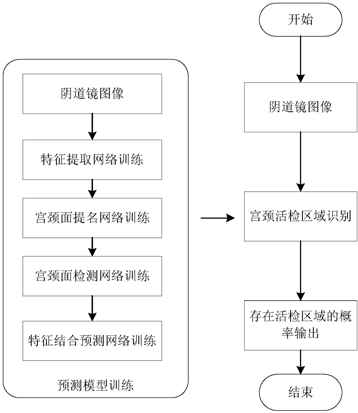
[0055] The cervical biopsy area identification device of the present invention comprises:

[0056] The image acquisition unit collects the normal saline image, acetic acid image and iodine image of the cervix and sends them to the data processing unit;

[0057] The data processing unit includes a trained cervical biopsy area recognition model, which analyzes and processes the normal saline image, acetic acid image and iodine image, and outputs the probability label of the cervical biopsy area;

[0058] Display the unit, get the probability label and display it.

[0059] According to the probability label output by the cervical biopsy area recognition device, combined with the patient's saline i...


PUM


Abstract

The invention discloses a cervical biopsy area identification method and a device based on a channel information multimodal network. The device comprises an image acquisition unit, a data processing unit and a display unit, wherein the image acquisition unit collects the physiological saline image, the acetic acid image and the iodine image of a cervix; the data processing unit includes a trainedcervical biopsy area identification model, analyzes and processes the physiological saline image, the acetic acid image and the iodine image and outputs a probability label for indicating that the cervix has a biopsy area; the cervical biopsy area identification model includes a detection network layer and a characteristic combination prediction network layer; the detection network layer is used for extracting characteristic graphs and positional information of cervical surface areas in the physiological saline image, the acetic acid image and the iodine image; the three characteristic graphsand the positional information are jointed on a channel dimension, and through characteristic fusion and identification, the probability label for indicating that the cervix has the biopsy area is output; and the display unit acquires and displays the probability label. The cervical biopsy area identification device can assist a doctor to make an accurate judgment on whether the cervix of a patient needs further biopsy.

Description

technical field [0001] The invention relates to the field of medical image processing, in particular to a method and device for identifying cervical biopsy regions based on channel information multimodal networks. Background technique [0002] Cervical cancer is the most common gynecological malignancy. The high-incidence age of carcinoma in situ is 30-35 years old, and that of invasive carcinoma is 45-55 years old. In recent years, the onset tends to be younger. [0003] The inspection steps of cervical lesions are mainly divided into three steps: (1) cervical cytology examination, the most commonly used is the Pap smear method; (2) colposcopy, if the cytology results are abnormal, colposcopy examination is required, observation Changes in cervical epithelial color, blood vessels, etc.; (3) Cervical tissue biopsy. If there is any doubt in colposcopy, the doctor will take a small amount of cervical tissue from the suspicious lesion for biopsy under the positioning of the co...

Claims


Application Information

Patent Timeline
Patent Type & Authority Applications(China)
IPC IPC(8): G06K9/62G06N3/04G06N3/08
CPCG06N3/08G06V2201/032G06N3/045G06F18/253G06F18/214
Inventor 吴健应兴德陈婷婷马鑫军吕卫国袁春女姚晔俪王新宇吴边陈为吴福理吴朝晖
Owner ZHEJIANG UNIV
Learn More