Variable-current variable-speed non-commutated permanent magnet direct current motor

A DC motor without commutation technology, which is applied in the direction of motors, electric vehicles, electric components, etc., can solve the problem of large power consumption and achieve the effects of low power consumption, high utilization rate of permanent magnet energy, and fast torque response

Pending Publication Date: 2018-07-24
甘肃永动电子科技发展有限公司
View PDF0 Cites 1 Cited by
  • Summary
  • Abstract
  • Description
  • Claims
  • Application Information

AI Technical Summary

Problems solved by technology

[0003] The purpose of the present invention is to provide a variable-flow variable-speed non-commutation permanent magnet DC motor to solve the problem that the existing DC motor consumes a large amount of electric energy to overcome the magnetic pull of the permanent magnet stator to the rotor

Method used


Image

  • Variable-current variable-speed non-commutated permanent magnet direct current motor
  • Variable-current variable-speed non-commutated permanent magnet direct current motor
  • Variable-current variable-speed non-commutated permanent magnet direct current motor

Examples


Embodiment Construction

[0021] The present invention is described in further detail now in conjunction with accompanying drawing.

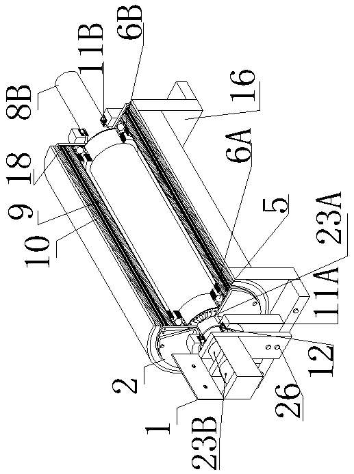
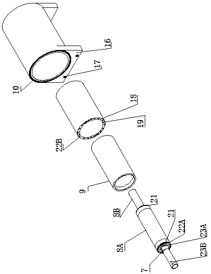
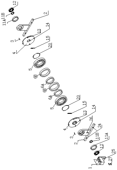
[0022] A variable-flow variable-speed non-commutation permanent magnet DC motor, including a machine base 16, a coil inner rotor 8A, a permanent magnet inner stator 9, a coil outer rotor 18, and a permanent magnet outer stator 10, and the coil inner rotor 8A is arranged on the permanent magnet inner stator 9, the permanent magnet inner stator 9 is arranged in the inner cavity of the coil outer rotor 18, the coil outer rotor 18 is arranged in the inner cavity of the permanent magnet outer stator 10, and the permanent magnet outer stator 10 is arranged on the base 16; It also includes rotor shaft 8B, rotor shaft support 2, rotor shaft magnetic suspension inner sleeve 6A, rotor shaft magnetic suspension outer sleeve 6B, support magnetic suspension inner sleeve 11B, support magnetic suspension coil outer sleeve 11A, and the two ends of rotor shaft 8B are arranged on two In t...


PUM


Abstract

The invention discloses a variable-current variable-speed non-commutated permanent magnet direct current motor, belongs to the field of direct current motors, and solves the problem that the existingdirect current motor consumes a lot of electric energy so as to overcome a magnetic pull of a permanent magnet stator to a rotor. The variable-current variable-speed non-commutated permanent magnet direct current motor comprises a pedestal, a coil inner rotor, a permanent magnet inner stator, a coil outer rotor and a permanent magnet outer stator, and further comprises a rotor shaft, rotor shaft supports, a rotor shaft magnetic levitation inner sleeve, a rotor shaft magnetic levitation outer sleeve, a support magnetic levitation inner sleeve and a support magnetic levitation outer sleeve, wherein the two ends of the rotor shaft are arranged inside support bearings of the two rotor shaft supports; the rotor shaft is tightly sleeved inside the inner cavity of the coil inner rotor; the rotorshaft magnetic levitation inner sleeve is sleeved inside external-diameter openings of the two ends of the coil inner rotor; the rotor shaft magnetic levitation outer sleeve is tightly sleeved insideinternal-diameter openings of the two ends of the permanent magnet inner stator. A high-power ultrahigh-speed permanent magnet direct current motor or generator can be manufactured as required; the variable-current variable-speed non-commutated permanent magnet direct current motor is applicable to the field, which needs power or power generation, of electric vehicles, industrial and mining enterprises and the like.

Description

technical field [0001] The invention belongs to the field of direct current motors, and in particular relates to a variable-flow variable-speed non-commutation permanent magnet direct-current motor. Background technique [0002] DC motors are divided into radial magnetic field and axial magnetic field according to the magnetic field structure, and the excitation method is divided into permanent magnet excitation and winding iron core excitation. They have one thing in common. Due to structural limitations such as size, permanent magnet materials cannot be large in size and mass. application, so the utilization rate of permanent magnet energy is low, and the current needs to be commutated, which consumes a lot of power. The existing permanent magnet DC motor adopts electromagnetic coils, axially surrounds on the radial annular drum iron core, and is arranged in the inner cavity of the single polarity drum-shaped permanent magnet stator. Its principle is; the permanent magnet ...

Claims


Application Information

Patent Timeline
Patent Type & Authority Applications(China)
IPC IPC(8): H02K16/00H02K1/17H02K1/22H02K5/16H02K5/22
CPCH02K1/17H02K1/22H02K5/161H02K5/225H02K16/00Y02T10/64
Inventor 马飞
Owner 甘肃永动电子科技发展有限公司
Why Eureka
Try Eureka