Headphone plug-and-plug detection circuit, headphone detection device and audio equipment

An earphone detection and detection circuit technology, applied in the detection field, can solve the problems of high research and development cost, circuit design limitations, crosstalk between internal channels, etc., and achieve the effect of low research and development cost, complete specifications, and reduced complexity.

Active Publication Date: 2021-01-29
LEADCORE TECH +1
View PDF7 Cites 0 Cited by
  • Summary
  • Abstract
  • Description
  • Claims
  • Application Information

AI Technical Summary

Problems solved by technology

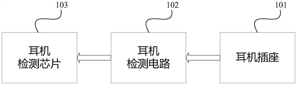
Specifically, please refer to Figure 5 As shown, the earphone detection chip 103 generally includes a microphone signal detection port MIC2_INP, an analog-to-digital converter ADC for performing analog-to-digital conversion on signals detected by the MIC2_INP detection port, a detection port HSDET for detecting earphone plug-in signals, and a The core module Mechanicalinsertion detection for judging the signal detected by the detection port and the corresponding operation, and the multiplexer module MUX for multiplexing the microphone and earphone, etc. When the HSDET detection port has a negative voltage, the internal ESD diode D1 will conduct forward , resulting in leakage current at the HSDET detection port, the leakage current path is as follows Figure 5 As shown by the thick black line in ; at the same time, due to the existence of negative voltage, the internal MUX cannot be completely closed, and when the MUX is accidentally opened, there will be crosstalk between internal channels
[0008] 2. It cannot be applied to high-level audio output solutions, otherwise it may cause wrong judgment of earphone insertion and extraction. Specifically, when it is used for ordinary audio output, its output voltage is about ±1.4V, such as Figure 6A As shown, V1=-V2=1.2V~1.4V, and when outputting HIFI audio with high-impedance headphones, the output voltage can reach about ±2.7V, such as Figure 6B As shown, V1=-V2=2.5V~2.7V, this is mainly because the internal operational amplifier U0 of the HIFI amplifier circuit directly works on the ±5V power supply, such as Figure 7 As shown, so when the NO-type headphone socket is connected with high-impedance headphones, the output level will be higher
[0009] In view of the above two shortcomings of the NO-type earphone socket, the existing technology has a circumvention plan in the actual product design and use process. One is to select a special earphone detection chip that supports the negative level detection port, so as to ensure the normal operation of the earphone detection chip. Work, this circumvention scheme has the following disadvantages: (1) high cost: due to the negative level requirements for the earphone detection chip, usually only a dedicated earphone detection chip can be selected, and the general cost is relatively high; (2) the design is limited : Because usually only a dedicated headphone detection chip (such as CODEC) will design a dedicated detection port that supports negative levels, and a general-purpose processor (such as a CPU) generally does not have such a special port, so the circuit design will be limited
The other is that when high-level audio output is required, instead of using the NO type earphone jack, only the NC type earphone jack can be used. This circumvention scheme has the following disadvantages: (1): Higher cost: as mentioned above, NC NC-type headphone jacks are more expensive than NO-type headphone jacks because of their complex internal structure; (2) High R&D costs: As mentioned above, NC-type headphone jacks have far fewer models than NO-type, so it often happens during the design stage. Structural engineers will spend a long time looking for an NC-type headphone jack with a matching structure, or conversely, they will be forced to modify the existing design in order to accommodate the existing NC-type headphone jack, so that the internal structure and appearance design of the product are different. Compromises and concessions; (3) Full customization of headphone sockets: If no headphone sockets with exactly matching structural specifications can be found and the R&D cannot compromise the design, then the design manufacturer can only customize the headphone sockets, but custom materials will cause additional problems, such as There are a series of problems such as independent development costs of suppliers, quality control risks of customized new materials, material inventory and production cycle, so the full customization of earphone sockets is the most costly and risky in all aspects.

Method used


Image

  • Headphone plug-and-plug detection circuit, headphone detection device and audio equipment
  • Headphone plug-and-plug detection circuit, headphone detection device and audio equipment
  • Headphone plug-and-plug detection circuit, headphone detection device and audio equipment

Examples


Embodiment Construction

[0038]In order to make the purpose and features of the present invention more comprehensible, the specific embodiments of the present invention will be further described below with reference to the accompanying drawings. However, the present invention can be implemented in different forms and should not be limited to the described embodiments.

[0039]Please refer toFigure 8 , The present invention proposes an earphone plug-in detection circuit, which includes a normally open earphone socket 802, an earphone detection circuit unit 803, and an earphone detection chip 804 that are sequentially connected, wherein the normally open earphone socket 802 includes a detection pin DET and A headphone audio path pin L that can be connected to and disconnected from the detection pin DET; the headphone detection circuit unit 803 includes a bias module 8031 ​​and a low-pass filter module 8032, the input end of the low-pass filter module 8032 The detection pin DET is connected, the output end is con...


PUM


Abstract

The invention provides an earphone plug-and-plug detection circuit, an earphone detection device, and an audio device. Through the earphone detection circuit unit mainly composed of a bias voltage module and a low-pass filter module, the design of related products does not limit the earphone socket and the earphone detection chip. The purpose of the type selection is that the R&D personnel do not need to consider whether the headphone detection chip supports negative voltage and whether the headphone jack is compatible with normal level and high level audio output when designing related products, so as to have more choices and more flexible design and lower costs.

Description

Technical field[0001]The invention relates to the field of detection technology, in particular to an earphone plug-in detection circuit, an earphone detection device and audio equipment.Background technique[0002]When the music playback device tries to play audio through the earphone, it needs to first check whether the earphone jack is inserted into the earphone, so as to ensure that the audio is switched to the earphone output only when the earphone is inserted; the same also needs to ensure that the earphone can be accurately detected. And perform corresponding operations, such as pausing playback or switching to speaker output.[0003]The earphone plug detection circuit is roughly divided into three modules, such asfigure 1 As shown, it is divided into a headphone socket 101, a headphone detection circuit unit 102, and a headphone detection chip 103. The headphone socket 101 is a headphone jack for fixing the headphone plug and ensuring a good electrical connection between the head...

Claims


Application Information

Patent Timeline
Patent Type & Authority Patents(China)
IPC IPC(8): H04R29/00
CPCH04R29/001
Inventor 凌忠海
Owner LEADCORE TECH
Why Eureka
Try Eureka