Laser marking method for die steel

A laser marking method and laser marking technology, which are applied in the field of laser marking of mold steel, can solve the problems of uneven shading, affecting the printing effect of products, marking on the surface, etc. Depth, clear and straight edges

Active Publication Date: 2018-07-27
HANS LASER TECH IND GRP CO LTD
View PDF7 Cites 8 Cited by
  • Summary
  • Abstract
  • Description
  • Claims
  • Application Information

AI Technical Summary

Problems solved by technology

[0005] In view of the above-mentioned deficiencies in the prior art, the object of the present invention is to provide a laser marking method for die steel, thereby overcoming the irregular edges and uneven shading in the method for marking the depth on the surface of die steel in the prior art, or It is only marked on the surface, which affects the pad printing effect of the product

Method used


Image

  • Laser marking method for die steel
  • Laser marking method for die steel
  • Laser marking method for die steel

Examples


Embodiment Construction

[0030] The present invention provides a laser marking method for die steel. In order to make the object, technical solution and effect of the present invention clearer and clearer, the present invention will be further described in detail below with reference to the accompanying drawings and examples. It should be understood that the specific embodiments described here are only used to explain the present invention, not to limit the present invention.

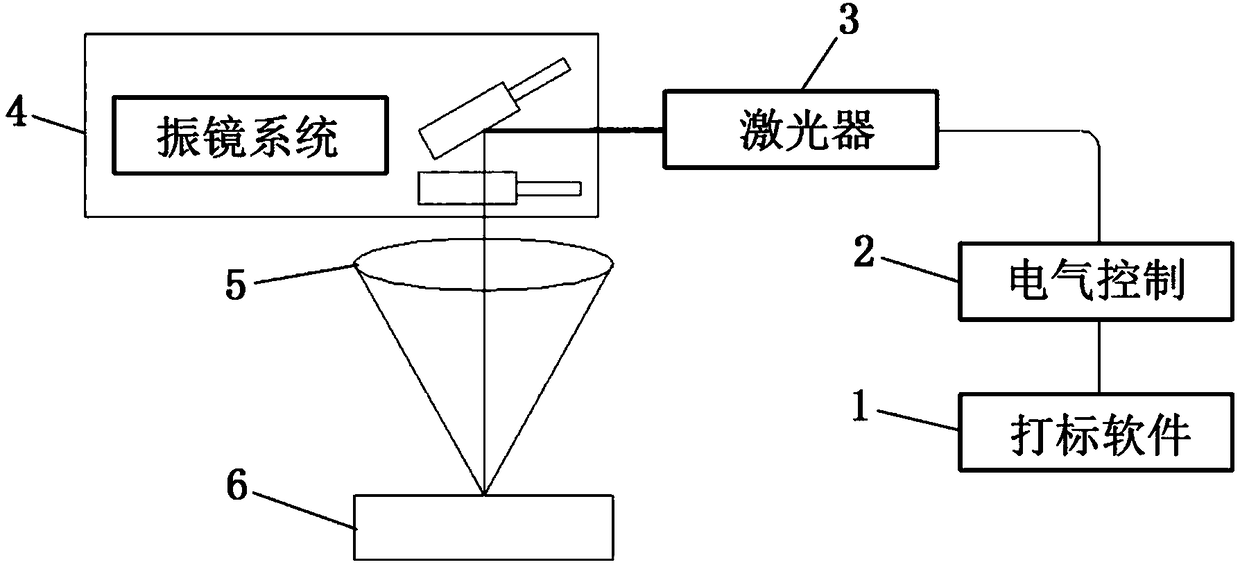
[0031] The laser marking equipment of the mold steel of the embodiment of the present invention, as figure 1 As shown, it includes: marking software 1, electrical control 2, laser 3, galvanometer system 4, focusing lens 5. Wherein, the marking software is used to call laser marking parameters for marking according to the position and size information of the die steel 6 . The electrical control is used to provide energy power to the laser and control the output mode of the laser beam. The laser is used to provide a laser ligh...


PUM


Abstract

The invention discloses a laser marking method of die steel. The method comprises the steps that a long pulse width laser with the pulse width of 90-110 ns is adopted, and laser marking is carried outon the die steel at the laser frequency of 45-55 kHz; and during marking, a filling distance of the laser is controlled to be 0.008-0.015 mm, and meanwhile, the laser marking speed is controlled to be 380-450 mm / s. According to the laser marking method, the laser with a long pulse width and a high frequency is adopted, marking machining is carried out on the die steel under the preferable fillingdensity and the low marking speed so that the instantaneous peak power can be guaranteed not to exist while enough heat can be guaranteed, and then the effect that steel on the surface of the die steel is removed through heating and vaporization and the bottom material is not damaged is achieved; and the shape of the part subjected to the steel removing and machining is consistent with the shapeof the unmachined part, the boundary is clear and straight, the surface is smooth, the hand feeling is free of depth and dirt resistance, the advantages of corrosion resistance and wear resistance ofthe die steel are perfectly reserved, and the machined die steel can be stored for a long time.

Description

technical field [0001] The invention relates to the technical field of laser processing, in particular to a laser marking method for die steel. Background technique [0002] With the diversification of consumer electronics market demand, more and more electronic product logos use pad printing instead of traditional silk screen printing. The principle of ink pad printing is: first etch the designed pattern on the printing plate, coat the etching plate with ink, and then transfer most of the ink to the printed object through the silicone head. Make electronic products present the content of the pad printing mold. Pad printing molds have more strict requirements, such as depth, size, edge, shading, etc. The most suitable depth for pad printing is 100-150μm. If it is too shallow, the ink will be less and the three-dimensional effect will not be strong. If it is too deep, the ink will overflow and the edges will feel burrs. [0003] The main component of die steel is iron, as ...

Claims


Application Information

Patent Timeline
Patent Type & Authority Applications(China)
IPC IPC(8): B23K26/362B23K26/60B23K103/04
CPCB23K26/361B23K26/60
Inventor 黄智斌王艺李鹤向军谢建平范醉风吴烈高云峰
Owner HANS LASER TECH IND GRP CO LTD
Why Eureka
Try Eureka