
Portable composite antenna supporting tube system

A technology of antenna support and composite materials, which is applied in the direction of antenna supports/installation devices, antennas, antenna parts, etc., and can solve the problem that the height of antenna support rods cannot be met, the requirements for rapid erection cannot be met, and the weight of metal antenna support rods is heavy. and other problems, to achieve the effect of convenient unfolding and rewinding, wide range of uses and high erection height

Pending Publication Date: 2018-07-27
WEIHAI GUANGWEI COMPOSITES
View PDF0 Cites 5 Cited by
  • Summary
  • Abstract
  • Description
  • Claims
  • Application Information

AI Technical Summary

Problems solved by technology

[0003] The main material of the existing antenna support rod system is metal: 1) One is to use multi-section metal pipe thread connection to meet the carrying requirements. When installing and dismounting, each section of thread needs to be screwed separately. erection requirements; at the same time, the weight of the metal antenna support rod is heavy, up to dozens of kilograms, which is not convenient for a single person to carry; 2) Another method is to use a jacket-type structural support rod with different diameter rods, but its erection height is limited. Limits, unable to meet the requirements for the height of the antenna support pole under various terrain conditions
Therefore, it is imminent to solve the problems of heavy weight of metal antenna support rods, rapid erection by one person, and super long erection height.

Method used


Image

  • Portable composite antenna supporting tube system
  • Portable composite antenna supporting tube system
  • Portable composite antenna supporting tube system

Examples


preparation example 1

[0023] Lay the 90°, -45° and 45° glass fiber epoxy prepregs on a cylindrical mold with a diameter of 80mm in the order of layering, the thickness of the prepreg is 1mm, and the length of the prepreg is 7m; After the impregnation is finished, wrap the peelable shaping tape on the surface of the prepreg; then it is cured in the oven, and the temperature is raised from room temperature to 80°C at 2.5°C / min, and kept for 40 minutes, and then heated to 130°C at 2.5°C / min. Keep the temperature for 60min; after the temperature is stopped, cool down with the furnace to below 70℃, and release the mold into semi-finished products; cut 50mm in the axial direction of the main body of the antenna support tube; treat the outer surface of the main body of the antenna support tube and glue the canvas, and turn over the edges. edge processing.

preparation example 2

[0025] The 90°, 0° and 90° glass fiber polyethylene thermoplastic prepregs are laid on the cylindrical core mold with a diameter of 120mm in the order of layering. The thickness of the prepreg is 1.5mm, and the length of the prepreg is 8m; after the prepreg is laid, it is put into the forming mold. The schematic diagram of the mold structure is as follows figure 1 Then put it into a hot press for heating and pressure molding, apply a pressure of 0.6Mpa, keep the temperature at 160°C for 3 minutes, cool down to below 50°C, and release it into a semi-finished product; the material has been opened during the production process, and no subsequent processing is required; The outer surface of the main body of the antenna support tube is treated and the canvas is glued, and the edges are flanged.

preparation example 3

[0027]The 24K carbon fiber is dipped in the dipping tank and then wound on a cylindrical mandrel with a diameter of 120mm according to the set angle. The fiber winding thickness is 1.5mm, the winding length is 9m, and the resin viscosity is 1000cps. After the winding is completed, the excess resin on the surface is scraped off. , laying the release cloth, wrapping the surface with a peelable shaping bag; then curing in the oven, heating from room temperature to 90 °C at 4 °C / min, and holding for 40 minutes, then heating up to 140 °C at 4 °C / min, and holding for 70 minutes; stop; After warming, cool down to below 70℃ with the furnace, demould into semi-finished products; cut 80mm axially along the main body of the antenna support tube; treat the outer surface of the main body of the antenna support tube and glue the canvas, and flange the edges.


PUM

PropertyMeasurementUnit
Opening sizeaaaaaaaaaa

Abstract

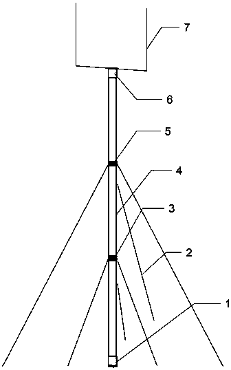
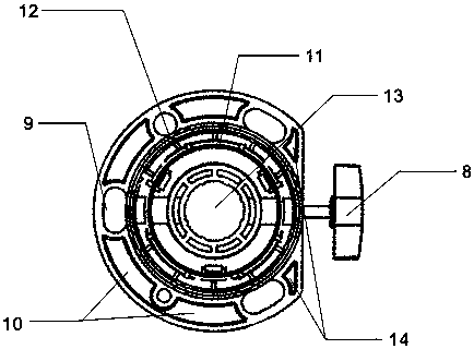
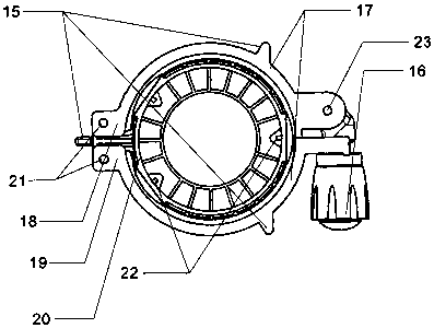
The invention relates to a portable composite antenna supporting tube system, belongs to the field of wireless communication antenna supporting devices. The portable composite antenna supporting tubesystem comprises an antenna supporting tube main body, wherein the antenna supporting tube main body is made into a cylindrical structure from a rolled composite material roll, the lower end and the upper end of the antenna supporting tube main body are respectively provided with a lower base and an upper base with the same integral structure, the tube wall of the antenna supporting tube main bodyis clamped between the inner base sleeve and the outer base sleeve which constitute the lower base and the upper base, the main body of the antenna supporting tube is provided with an upper sleeve pipe and a lower sleeve pipe with the same structure, the upper sleeve pipe and the lower sleeve pipe comprise a wind rope hole, a locking handle, an outer sleeve pipe and an inner sleeve pipe, the outer sleeve pipe is composed of an upper outer sleeve pipe and a lower outer sleeve pipe, one end of the upper outer sleeve pipe and the lower outer sleeve pipe are hinged with each other through a movable shaft, the other end of the upper outer sleeve pipe and the lower outer sleeve pipe are locked by a hinged locking handle, and the tube wall of the antenna supporting tube main body is locked between the outer sleeve pipe and the inner sleeve pipe through a locking handle, the antenna penetrates through the lower base hole in the middle part of the lower base, passes through the lower sleeve pipe and the upper sleeve pipe in sequence, and finally passes through the upper base hole in the middle part of the top upper base.

Description

technical field [0001] The invention relates to the field of wireless communication antenna support devices, in particular to a portable composite material antenna support tube system, which is applied to the fields of communication, military, transportation and the like. signal coverage. Background technique [0002] As we all know, modern wars and emergencies such as earthquakes have extremely high requirements for communication support capabilities, and communication support capabilities under complex terrain and environments are very important. As a common accessory in the communication field, the antenna support rod directly determines the height, speed and stability of the antenna erection, and needs to meet the requirements of light weight, rapid erection, and terrain adaptability. [0003] The main material of the existing antenna support rod system is metal: 1) One is to use multi-segment metal pipe thread connection to meet the carrying requirements. When installi...

Claims


Application Information

Patent Timeline
IPC IPC(8): H01Q1/12
CPCH01Q1/12H01Q1/1207
Inventor 林凤森陈良倪亭隋显航
Owner WEIHAI GUANGWEI COMPOSITES
Learn More