
Rotor position error compensation method for permanent-magnet synchronous motor based on high-frequency signal injection method

A permanent magnet synchronous motor, rotor position error technology, applied in the direction of control generator, motor generator control, control electromechanical transmission, etc., can solve problems such as rotor position estimation error, achieve the effect of improving accuracy and eliminating position error

Inactive Publication Date: 2018-07-27
WUHAN UNIV OF TECH
View PDF5 Cites 23 Cited by
  • Summary
  • Abstract
  • Description
  • Claims
  • Application Information

AI Technical Summary

Problems solved by technology

And it can solve the rotor position estimation error caused by inverter dead zone and filter

Method used


Image

  • Rotor position error compensation method for permanent-magnet synchronous motor based on high-frequency signal injection method
  • Rotor position error compensation method for permanent-magnet synchronous motor based on high-frequency signal injection method
  • Rotor position error compensation method for permanent-magnet synchronous motor based on high-frequency signal injection method

Examples


Embodiment Construction

[0028] The present invention will be described in further detail below in conjunction with the accompanying drawings.

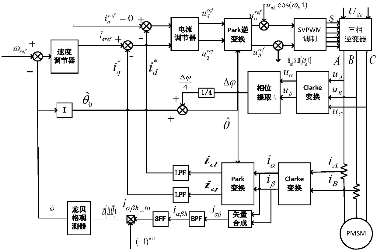
[0029] The present invention provides a permanent magnet synchronous motor rotor position estimation and error compensation method based on a new high-frequency signal injection method, wherein the high-frequency rotation injection method used by the Romberg observer estimates the rotor position and directly compensates the error. The block diagram is as follows figure 1 As shown, the specific steps are as follows:

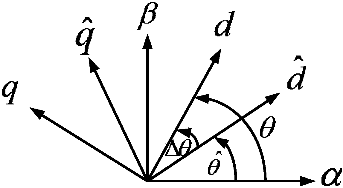
[0030] Step 1, establish a coordinate relationship diagram, such as figure 2 As shown, d-q is the actual synchronous rotating coordinate system, In order to estimate the rotor synchronous rotating coordinate system, α-β is the actual two-phase stationary coordinate system, and define the estimated position error where θ is the actual rotor position, To estimate the rotor position, The initial value of is 0.

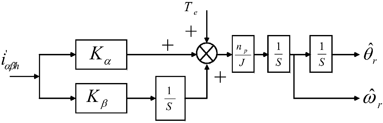
[0031] Step 2, such as fig...


PUM


Abstract

The invention discloses a rotor position error compensation method for a permanent-magnet synchronous motor based on a high-frequency signal injection method. The method comprises the steps that on the basis of the traditional rotary high-frequency voltage signal injection method, a Romberg observer is utilized as a novel position observer, a rotation speed estimation module is improved, and therefore the high-performance rotation speed estimation is achieved. A phase-locked loop is utilized to detect a phase error to directly compensate for a rotor position error. According to the method, theanti-load interference capability is high, the robustness to parameter changes is good, and by adopting a direct compensation method, the position detection accuracy of the rotary high-frequency voltage signal injection method is effectively improved.

Description

technical field [0001] The invention belongs to the field of motor control, and relates to a permanent magnet synchronous motor rotor correction method, in particular to a permanent magnet synchronous motor rotor position error compensation method based on a high-frequency signal injection method. Background technique [0002] Permanent magnet synchronous motors have the advantages of high precision, high dynamic performance, and high reliability, and are widely used in occasions that require high precision and high reliability. In the traditional permanent magnet synchronous motor speed control system, the rotor position of the motor is measured by Hall sensors, photoelectric encoders or resolvers. The advantage of the Hall sensor is low cost, but the disadvantage is that the accuracy is low; the precision of the photoelectric encoder can be made relatively high, but the cost is high, and the reliability is poor, so it is not suitable for harsh environments (high temperatur...

Claims


Application Information

Patent Timeline
Patent Type & Authority Applications(China)
IPC IPC(8): H02P21/18H02P21/14
CPCH02P21/18H02P21/14
Inventor 胡红明方贺肖寒刘雪骄
Owner WUHAN UNIV OF TECH
Learn More