Stepping combustion furnace

A combustion furnace, step-by-step technology, applied in the field of seamless steel pipe processing, can solve the problems of surface temperature difference, waste gas consumption, uneven heating temperature, etc., achieve the effect of small temperature difference change, reduce consumption, and uniform heating

Inactive Publication Date: 2018-07-31
CHANGSHUSMLESS STEEL TUBE
View PDF6 Cites 0 Cited by
  • Summary
  • Abstract
  • Description
  • Claims
  • Application Information

AI Technical Summary

Problems solved by technology

In order to make the pipe body and the furnace chamber reach and maintain the ideal temperature, the current stepping combustion furnace often adopts the structure of the electromagnetic valve pulse control burner on the side of the furnace body to heat the pipe body and keep the furnace chamber warm. This structure is used in practice. The deficiencies in the furnace are: when heating, the furnace pressure is low when the side burns downward, and it is easy to cause black stripe marks on the pipe body at the moving position of the fixed beam, causing a temperature difference on the surface, and when the furnace body stops burning, the temperature difference in the furnace chamber and The atmosphere fluctuates greatly, and it is easy to oxidize the surface of the tube body. Therefore, when there is a large temperature difference in the furnace cavity, it is necessary to open the solenoid valve and pass in proportionally mixed air and gas to continuously burn and heat the furnace cavity. However, this heating method Not only is the heating temperature uneven, which cannot reduce the surface oxidation of the pipe body involved above, but also the firepower cannot be adjusted smoothly, which wastes gas consumption

Method used


Image

  • Stepping combustion furnace

Examples


Embodiment Construction

[0015] In order to enable the examiners of the patent office, especially the public, to understand the technical essence and beneficial effects of the present invention more clearly, the applicant will describe in detail the following in the form of examples, but none of the descriptions to the examples is an explanation of the solutions of the present invention. Any equivalent transformation made according to the concept of the present invention which is merely formal but not substantive shall be regarded as the scope of the technical solution of the present invention.

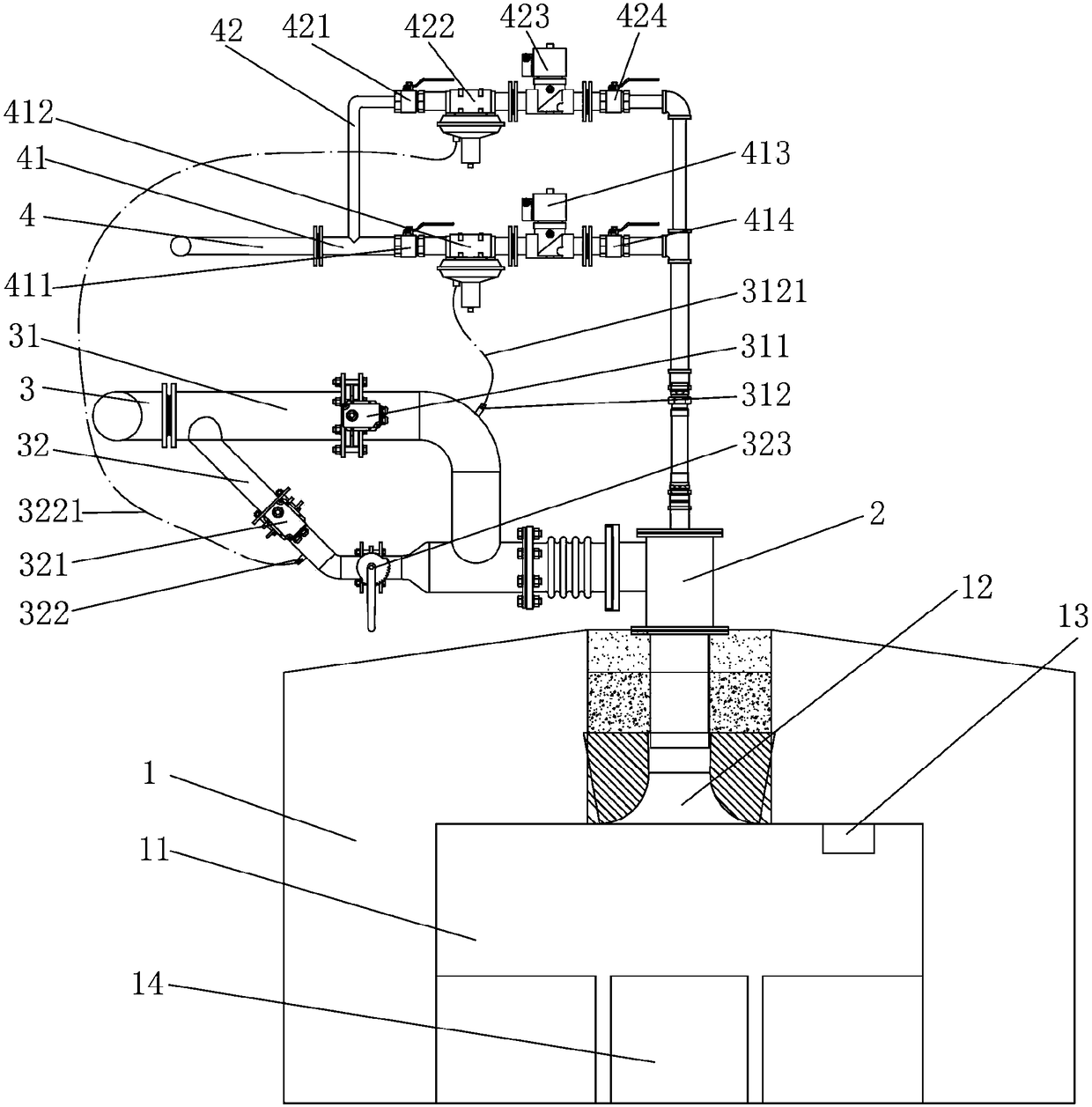
[0016] In the following descriptions, all concepts involving directionality or orientation of up, down, left, right, front and back are aimed at the current figure 1 As far as the position and state of the present invention are concerned, it cannot be understood as a special limitation on the technical solution provided by the present invention.

[0017] see figure 1 , the present invention relates to a walk...


PUM


Abstract

The invention relates to a stepping combustion furnace. The stepping combustion furnace comprises a furnace body, wherein a nozzle is formed in the top of a furnace chamber of the furnace body, a temperature sensing device is arranged on the inner wall of the furnace chamber of the furnace body, the flaming end of the nozzle extends into the nozzle, the upper end of the nozzle is respectively connected with a combustion-supporting air pipe and a gas pipe, high and low-flame combustion-supporting air pipes of which both ends communicate with each other are formed in the combustion-supporting air pipe, a high-flame analog quantity actuator and a high-flame air volume sampling head are arranged on the high-flame combustion-supporting air pipe, a low-flame analog quantity actuator and a small-flame air volume sampling head are arranged on the low-flame combustion-supporting air pipe, high and low-flame gas pipes of which both ends communicate with each other are formed on the gas pipe, a high-flame proportional valve and a high-flame electromagnetic valve are arranged on the high-flame gas pipe, a low-flame proportional valve and a low-flame electromagnetic valve are arranged on the low-flame gas pipe, the high-flame proportional valve and the low-flame proportional valve communicate with the high-flame air volume sampling head and the small-flame air volume sampling head respectively by virtue of high and low-flame sampling pipes, and the high and low-flame analog quantity actuators and the high and low-flame electromagnetic valves are respectively connected with the temperature sensing device. Black strips cannot be generated on a pipe body, so that the heating is uniform; the pipe body is prevented from being oxidized, so that the gas consumption is reduced.

Description

technical field [0001] The invention belongs to the technical field of seamless steel pipe processing, and in particular relates to a walking type combustion furnace. Background technique [0002] The processing of seamless steel pipes needs to go through more than ten processes. Among them, the pipe blanks need to be heat-treated before the pipe blanks are pierced by a piercer, and the steel pipes also need to be annealed after the seamless steel pipes are processed. The above heat treatment process You need to use a walking furnace to gradually heat the tube. In order to make the pipe body and the furnace chamber reach and maintain the ideal temperature, the current stepping combustion furnace often adopts the structure of the electromagnetic valve pulse control burner on the side of the furnace body to heat the pipe body and keep the furnace chamber warm. This structure is used in practice. The deficiencies in the furnace are: when heating, the furnace pressure is low wh...

Claims


Application Information

Patent Timeline
IPC IPC(8): F27B9/36F27B9/20F27B9/40
CPCF27B9/36F27B9/201F27B9/40F27B2009/3615F27M2001/1556
Inventor 周国强吴益周云峰杨中保许卫明顾瑞君金雪忠郭建华
Owner CHANGSHUSMLESS STEEL TUBE
Why Eureka
Try Eureka