High-efficiency broadband horn array antenna

An array antenna and broadband horn technology, which is applied in the field of electromagnetic reflection unit unit devices, can solve the problem that the requirements of the broadband horn array antenna cannot be well satisfied, and achieves the effects of high bandwidth, simple structure and low characteristic impedance.

Pending Publication Date: 2018-07-31
NO 54 INST OF CHINA ELECTRONICS SCI & TECH GRP
View PDF0 Cites 7 Cited by
  • Summary
  • Abstract
  • Description
  • Claims
  • Application Information

AI Technical Summary

Problems solved by technology

[0003] Therefore, none of the existing antenna schemes can better meet the requirements of the broadband horn array antenna

Method used


Image

  • High-efficiency broadband horn array antenna
  • High-efficiency broadband horn array antenna
  • High-efficiency broadband horn array antenna

Examples


Embodiment Construction

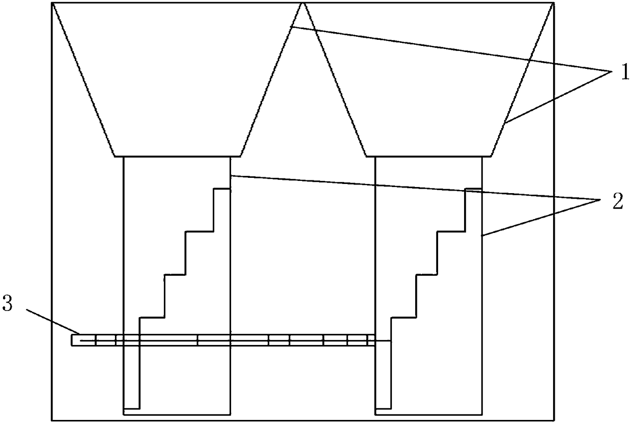
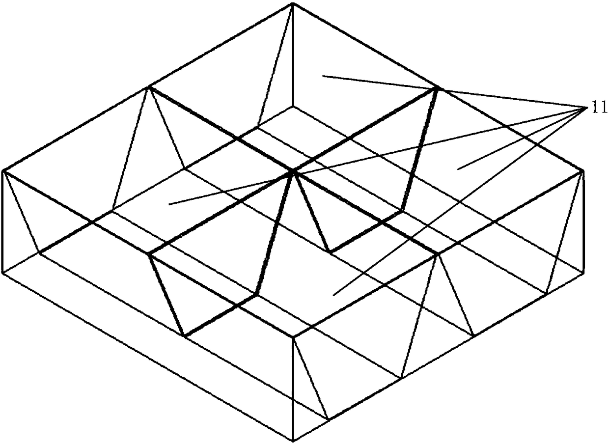
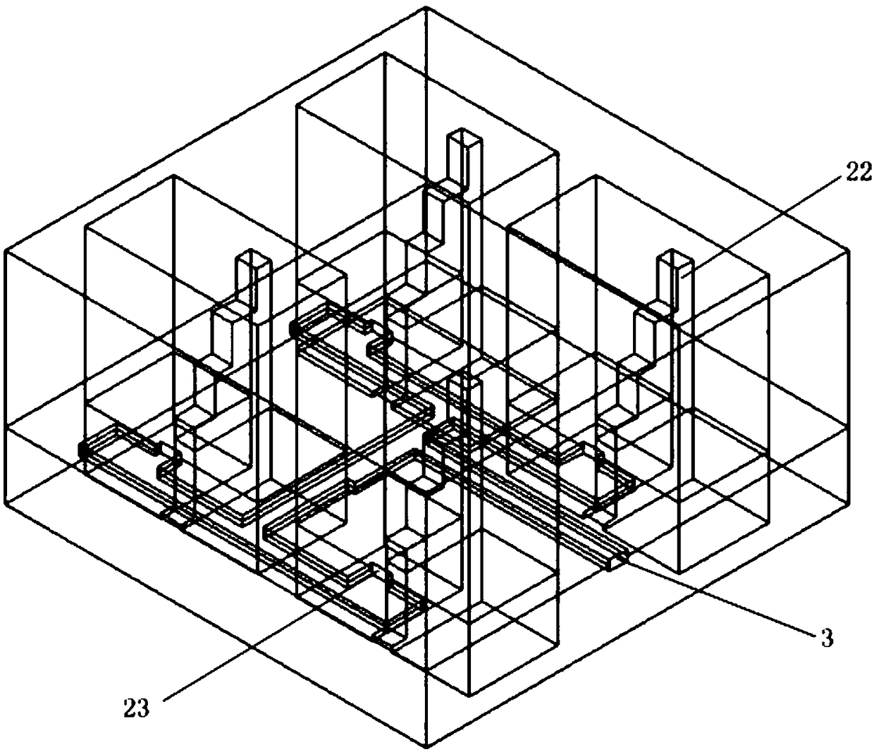
[0027] According to the attached Figure 1-4 The present invention is described further:

[0028] A high-efficiency broadband horn array antenna. The array antenna is composed of multiple horn antennas. Each horn antenna is arranged in 4*4. Each antenna unit shares a partition with adjacent antenna units. The resonant cavity of each horn antenna is 2 A single ridge portion 22 is constructed inside, and the single ridge portion extends upwards from the bottom of the resonator 2, and the lower edge of the radiation port 11 of the horn antenna is located above the single ridge portion 22, and the single ridge portion The top of the part is connected to the bottom edge of the radiation port 11 or there is a gap between the top of the single ridge part and the bottom edge of the radiation port, and a gap for coupling signals is left between the bottom of the single ridge part and the resonant cavity Coupling slots 23 are connected to striplines at the bottom of each horn antenna, ...


PUM


Abstract

The invention discloses a broadband horn array antenna, and especially relates to a high-efficiency antenna array which can effectively improve the bandwidth of a horn antenna and has a simple ridgedhorn structure. The array antenna is structurally composed of a plurality of horn antennas, wherein the internal part of a resonant cavity of each horn antenna is provided with a single ridge piece part, each single ridge piece part extends upwards from the bottom of the corresponding resonant cavity, the lower edge of a radiation port of each horn antenna is located above the corresponding singleridge piece part, a coupling slot used for coupling signals is reserved between the bottom of each single ridge piece part and the corresponding resonant cavity, the bottom of each horn antenna is connected with a strip line, each strip line extends into the coupling slot of the corresponding horn antenna, and the strip lines are synthesized through a broadband power divider to form an output signal. The broadband horn array antenna adopts the combination of the traditional horn array and ridge waveguide broadband feed, and achieves a purpose of high efficiency of a broadband antenna. Compared with the traditional horn array, the bandwidth is greatly improved; and compared with the general ridged horn antenna, the efficiency is high.

Description

technical field [0001] The invention relates to the field of electromagnetic reflection unit unit devices, and in particular provides a high-efficiency antenna array with a ridged horn structure that can effectively improve the bandwidth of the horn antenna and has a simple structure. Background technique [0002] The conventional horn antenna is used as a broadband array antenna unit. The disadvantage is that the size of the resonant cavity is large, resulting in too small space for the array feed network to arrange the wires, which cannot meet the requirements; the conventional ridged horn can achieve ultra-wideband, but the disadvantage is that the structure is complex and difficult to process. Usually Use as an independent speaker or feed. As a unit, its size exceeds one wavelength, and grating lobes and other phenomena will appear in the high-frequency pattern when the array is assembled. [0003] Therefore, none of the existing antenna solutions can better meet the re...

Claims


Application Information

Patent Timeline
Patent Type & Authority Applications(China)
IPC IPC(8): H01Q21/00H01Q13/02H01Q1/50
CPCH01Q21/0075H01Q1/50H01Q13/0233H01Q13/0275
Inventor 张瑞东牛传峰赵航赵东贺李栋何其洪
Owner NO 54 INST OF CHINA ELECTRONICS SCI & TECH GRP
Why Eureka
Try Eureka