This helps you quickly interpret patents by identifying the three key elements:
Problems solved by technology
Method used
Benefits of technology
Problems solved by technology
[0009] The purpose of the present invention is to solve the problem that the existing internal high pressure forming machine can only realize the linear loading of the bulging pressure, but cannot realize the pulsating loading, and then propose a high pressure forming method
Method used
Image
Click on the blue label to locate the original text in one second.
Reading with bidirectional positioning of images and text.
Examples
Embodiment 1
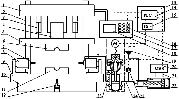
[0039] This embodiment is internal high pressure forming with conventional linear loading of bulging pressure, combined with Figure 1-6 This embodiment will be described.
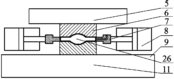
[0040] A small and medium-sized internal high pressure forming machine with bulging pressure pulsation loading according to the present invention, comprising: an upper beam 1, four guide columns 2, two fast cylinders 3, a main cylinder 4, a movable beam 5, an upper mold 6, two (or three) axial feed cylinder 8 and the same number of punches 7, workbench 9, frame 10, lower die 11, lower cylinder 12, electrical control cabinet 13, PLC (including AD / DA module) 14. Servo driver 15, multiple button switches 16, control panel 17, touch screen 18, low-pressure liquid filling system 19, host hydraulic system 20, system oil pipe 21, booster cylinder 22, pulsation hydraulic pressure generating device 23, high-pressure water pipe 24, pressure Transmitter 25.
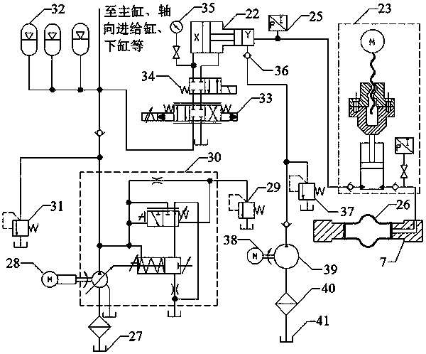
[0057] This embodiment is internal high pressure forming with sinusoidal pulsation loading of bulging pressure, combined with Figure 1-7 This embodiment will be described.
[0058] In this embodiment, the internal pressure loading curve function is:
[0059] P 1 (t)=P 0 (t)+ΔPsin(2πωt)
[0060]
[0061] In the formula, ΔP is the pulse wave amplitude, which is 5 MPa in this embodiment; ω is the pulse frequency, which is 1 Hz in this embodiment.
[0062] Compared with Example 1, when the pulsating loading method is selected as 1, the amplitude h needs to be manually measured before the part is formed. Because the system only feeds back and controls the conventional linearly loaded pressure, the pulsating pressure is partially open-loop controlled, and the input program is the amplitude h of the piston rod of the pulsating cylinder, not the amplitude ΔP of the pulsating pressure. Knowing the hydrodynamic properties of the forming medium, the pulsating cylinder, high-pres...
Embodiment 3
[0067] This embodiment is internal high pressure forming with rectangular pulsating loading of bulging pressure, combined with Figure 1-9 , Figure 8 This embodiment will be described.
[0068] In this embodiment, the internal pressure loading curve function is:
[0069]
[0070]
[0071] In the formula, ΔP is the pulse wave amplitude, which is 5 MPa in this embodiment; ω is the pulse frequency, which is 1 Hz in this embodiment.
[0072] Compared with Embodiment 2, the servo motor 49 drives the piston rod 46 to move at the maximum rotational speed in each pulsation period. The piston rod 46 moves quickly from the balance point to the maximum amplitude h, pauses for a period of time, then descends to the position h below the balance point, and quickly returns to the balance point when the pause is the same.
PUM
Abstract
The invention relates to a high-pressure forming method. Program parameters are processed by a PLC, and the action of each system and component is controlled separately; electrical signals are input to an electro-hydraulic servo valve, the feed of a pressure cylinder is controlled through the control over the flow of the servo valve; the liquid forming medium supplemented by a low pressure liquid-filling system flows into a pulsation hydraulic generating device through pressurizing the pressure cylinder; a piston rod in the pulsation hydraulic generating device is locked tightly and the high-pressure forming medium finally flows into a pipe; the outlet end of pressure cylinder is provided with a pressure transmitter to detect pressure, and the pressure is converted into the electric signals to be fed back and input into the PLC, a semi-closed loop control is formed through a PID controller in the PLC; and the high-pressure forming method expands the process application range of the equipment and improves the forming quality of the product.
Description
[0001] This application is a divisional application of the invention patent application "A Medium and Small-sized Internal High Pressure Forming Machine Loaded with Bulging Pressure Pulse". [0002] The original filing date: 2016-12-20. [0003] Original application number: 2016111868407. [0004] The name of the original invention: a small and medium-sized internal high pressure forming machine with bulging pressure pulsation loading. technical field [0005] The high-pressure forming method of the invention belongs to the technical field of special processing. Background technique [0006] Internal high pressure forming technology is an advanced, special, precise (semi-precision) net forming technology used to produce thin-walled metal components with complex cross-sections. Technology, with the characteristics of low cost, less process, light weight and high strength, is widely used in aviation, automobiles, home appliances and other fields. For example, multi-pass oil...
Claims
Application Information
Patent Timeline
Application Date:The date an application was filed.
Publication Date:The date a patent or application was officially published.
First Publication Date:The earliest publication date of a patent with the same application number.
Issue Date:Publication date of the patent grant document.
PCT Entry Date:The Entry date of PCT National Phase.
Estimated Expiry Date:The statutory expiry date of a patent right according to the Patent Law, and it is the longest term of protection that the patent right can achieve without the termination of the patent right due to other reasons(Term extension factor has been taken into account ).
Invalid Date:Actual expiry date is based on effective date or publication date of legal transaction data of invalid patent.