Turbine moving blade with bevelled prism cavities formed in blade top

A technology of moving blades and prisms, applied in the direction of supporting components of blades, mechanical equipment, engine components, etc., can solve the problems of increased leakage flow, increased lateral pressure gradient, increased cascade loss, etc., achieving obvious hindrance and enhanced wearability The effect of resistance, small gap allowable value

Inactive Publication Date: 2018-08-03
HARBIN INST OF TECH
View PDF2 Cites 1 Cited by
  • Summary
  • Abstract
  • Description
  • Claims
  • Application Information

AI Technical Summary

Problems solved by technology

On the one hand, separation flow will be generated inside the gap due to wall shearing; on the other hand, the leakage flow out of the gap forms a leakage vortex on the suction side, which is mixed with the mainstream fluid such as the upper channel vortex and blade radial fluid, and finally leads to the flow in the blade end region. Complicated, the cascade loss increases, which has a great impact on the efficiency and overall performance of the turbine
Especially in recent years, with the increase of turbine load, the lateral pressure gradient increases, which makes the leakage flow intensified and the cascade loss further increases

Method used


Image

  • Turbine moving blade with bevelled prism cavities formed in blade top
  • Turbine moving blade with bevelled prism cavities formed in blade top
  • Turbine moving blade with bevelled prism cavities formed in blade top

Examples


Embodiment Construction

[0024] It should be noted that, in the case of no conflict, the embodiments of the present invention and the features in the embodiments can be combined with each other.

[0025] The invention will be described in detail below with reference to the accompanying drawings and examples.

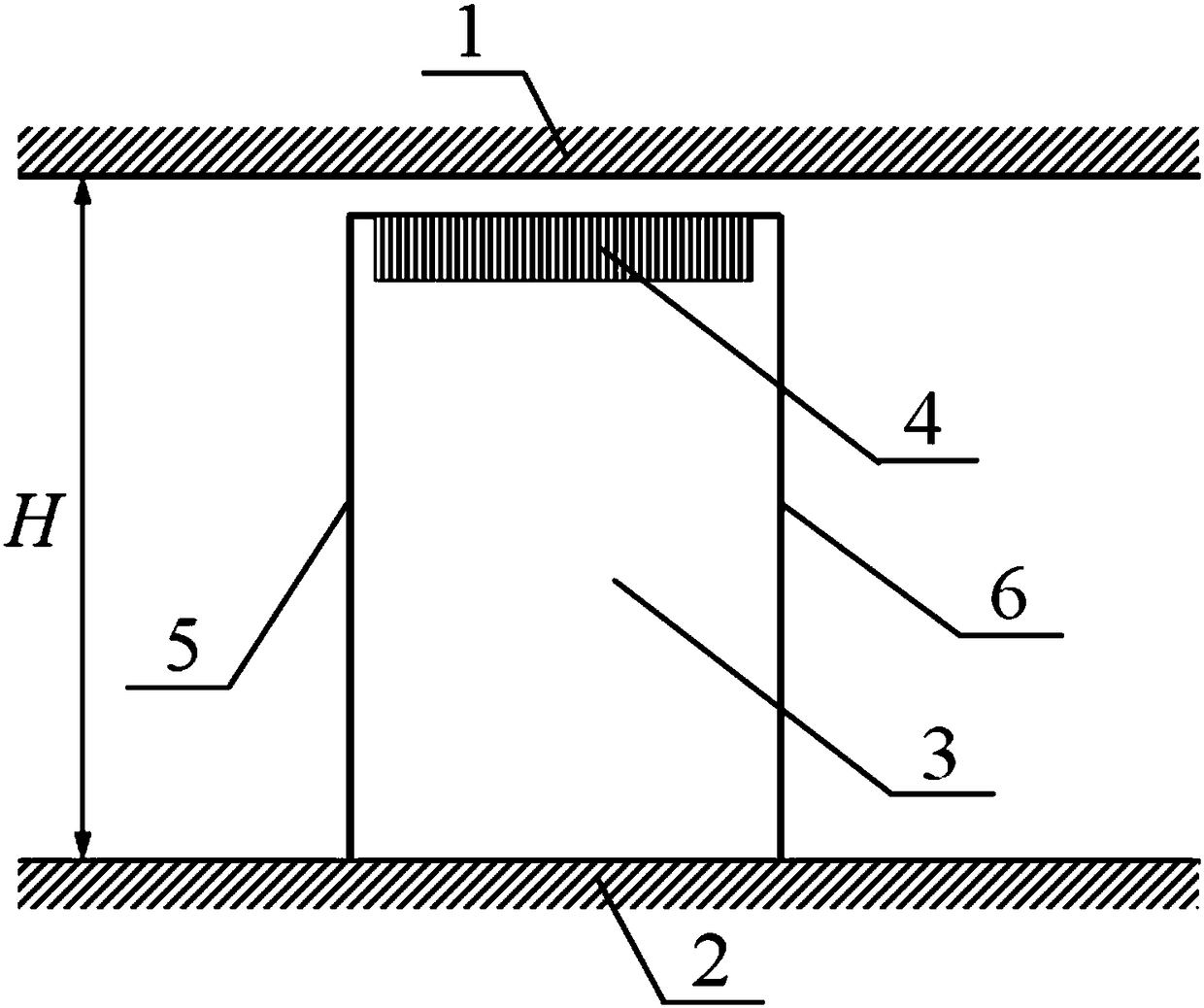
[0026] Such as figure 1 As shown, a turbine moving blade with a chamfered prism concave cavity on the top of the blade is used in the turbine moving blade. The blade body 3 is installed on the hub 2, and a cascade flow channel is formed between the casing 1 and the hub 2. 5. 6 denote the leading edge line and the trailing edge line of the blade body 3 respectively, and several chamfered prismatic concave cavities 4 are arranged on the tip of the blade body 3 from the leading edge to the trailing edge.

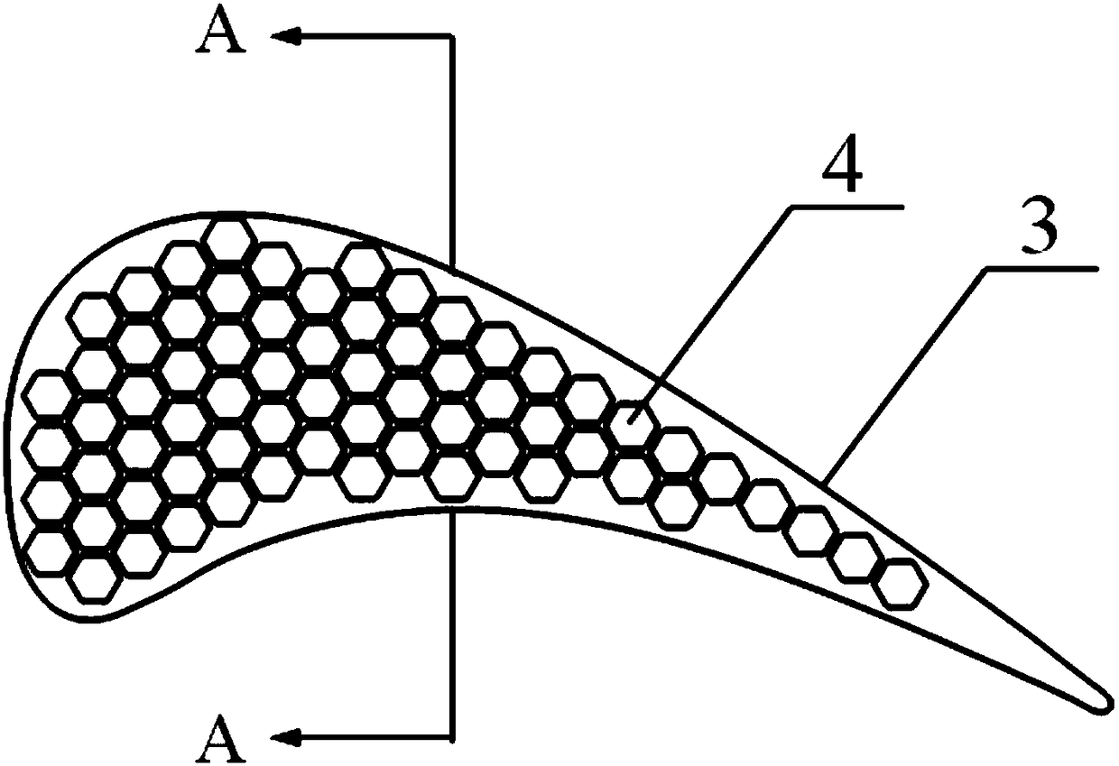
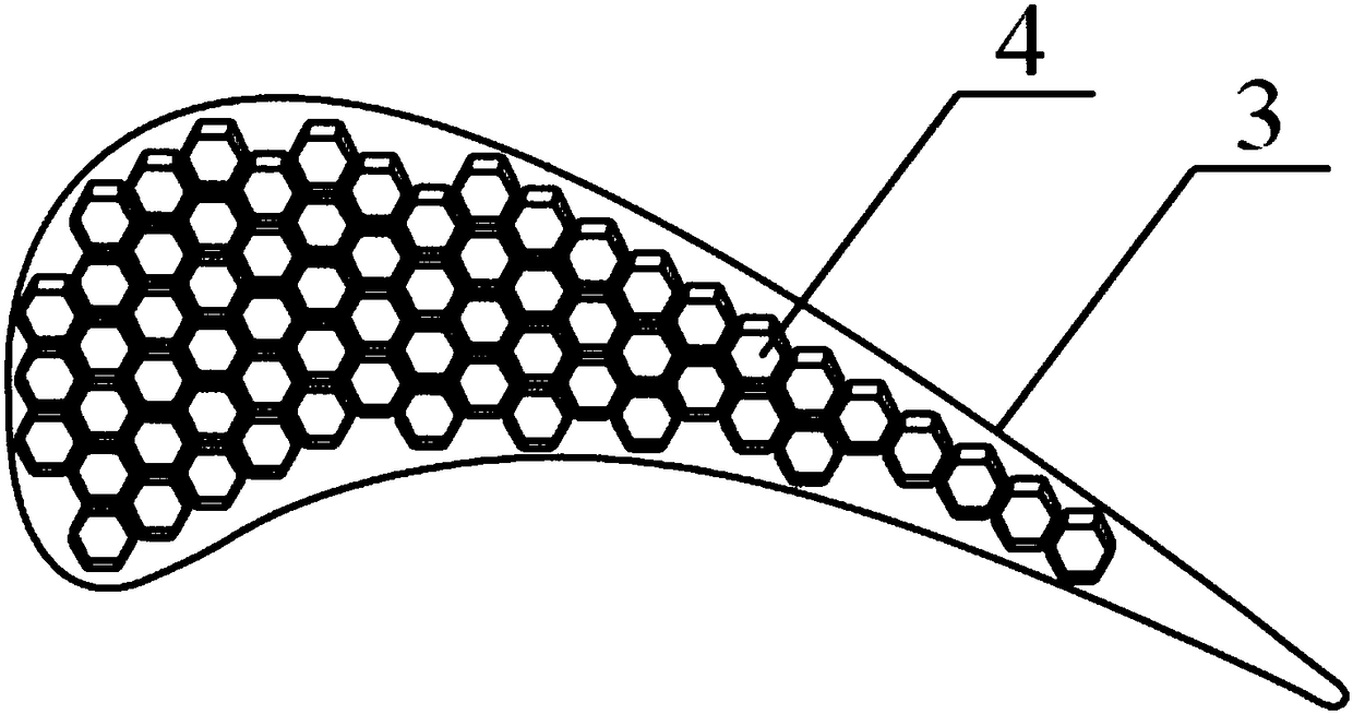
[0027] Such as Figure 2a and Figure 2b Shown are the specific arrangement forms of regular prism cavity with beveled bottom surface and oblique prism cavity with beveled bottom surface on th...


PUM


Abstract

The invention provides a turbine moving blade with bevelled prism cavities formed in a blade top. The turbine moving blade comprises a blade body, the multiple bevelled prism-shaped cavities are formed in the blade top of the blade body from the front edge to the tail edge, the bottom faces of the prism-shaped cavities adopt a bevelled mode, the ratio of the maximum height of the prism-shaped cavities to the height of the blade body is 0.5%-4%, and the beveled angles for beveling the bottom faces of the prism-shaped cavities are within the range of 30-60 degrees. According to the turbine moving blade with the bevelled prism cavities formed in the blade top, a part of leakage fluid entering a gap enters the prism-shaped cavities to be curled up to form vortexes, on the one hand, kinetic energy of the gap fluid is dissipated, on the other hand, the jet blocking effect on the gap fluid above the cavities is formed, then the purpose of controlling blade tip leakage flow of a turbine is achieved, the bottom faces of the prism cavities are beveled, the vortex intensity and development direction of the vortexes in the cavities are changed, the mixing effect of the fluid flowing into/flowing out of the cavities and the fluid in the gaps on the upper portion is enhanced, inhibiting turbine blade tip leakage flow is more advantageous, and the structure is simple.

Description

technical field [0001] The invention belongs to the technical field of turbines, and in particular relates to a turbine moving blade with a chamfered prismatic cavity provided on the top of the blade. Background technique [0002] There must be a certain tip clearance between the rotating blades and the casing inside the turbine. Due to the existence of the tip clearance, the tip clearance leakage flow must be formed under the action of the lateral pressure gradient on both sides of the blade pressure surface and suction surface. On the one hand, separation flow will be generated inside the gap due to wall shearing; on the other hand, the leakage flow out of the gap forms a leakage vortex on the suction side, which is mixed with the mainstream fluid such as the upper channel vortex and blade radial fluid, and finally leads to the flow in the blade end region. Complicated, the cascade loss increases, which has a great impact on the efficiency and overall performance of the tu...

Claims


Application Information

Patent Timeline
Patent Type & Authority Applications(China)
IPC IPC(8): F01D5/14
CPCF01D5/147F01D5/148
Inventor 俞建阳陈浮付云峰
Owner HARBIN INST OF TECH
Why Eureka
Try Eureka