Eureka AIR delivers breakthrough ideas for toughest innovation challenges, trusted by R&D personnel around the world.

Difference frequency terahertz quantum cascade laser

A quantum cascade, laser technology, used in lasers, phonon exciters, laser components and other directions, can solve the problems of large threshold, limited difference frequency tuning range, narrow gain spectrum, etc., to improve power and increase non-radiative attenuation. Longevity, performance improvement effect

Inactive Publication Date: 2018-08-03
INST OF SEMICONDUCTORS - CHINESE ACAD OF SCI
View PDF8 Cites 8 Cited by
  • Summary
  • Abstract
  • Description
  • Claims
  • Application Information

AI Technical Summary

Problems solved by technology

The output power of DFG THz QCL is positively correlated with the second-order nonlinear coefficient of the active region and the power of the two mid-infrared pump sources. The nonlinear effect comes from the strong coupling between quantum states. The theoretical calculation of the second-order nonlinear coefficient can reach 10 5 ~10 6 pm / V, which is 3 to 4 orders of magnitude higher than that of traditional nonlinear crystals. Usually, the dual active regions of difference-frequency terahertz quantum cascade lasers are composed of InGaAs / InAlAs quantum well barrier pairs. The active region design Mechanisms include double phonon resonance and bound state to continuous state dual active region structure, double single phonon resonance active region structure, the former only bound state to continuous state nuclear region can produce larger nonlinear effects, and bound state to continuous Compared with the single phonon resonance mechanism, the lifetime of the upper energy state of the optical transition has been improved from 0.39ps to 0.46ps. The power is still far less than the dual-core design, and the second-order nonlinear coefficients based on these structures are all in the range of 10 4 pm / V level, so the design mechanism of changing the active region based on the ordinary quantum well active layer structure has little room to improve device performance, and the device still has the problem of low power and power conversion efficiency
Since the quantum well only restricts the electrons in one direction, the electrons are still nearly free to move in the plane, so the upper and lower subbands participating in the transition are actually two continuous bands, and the energy overlap is not absolutely isolated. For mid-infrared QCLs, although their band bottom energy difference is much larger than the optical phonon energy of the bulk material, there is still a state with an energy difference equal to an optical phonon energy between the upper and lower subbands, so the electrons in the upper energy state The effective non-radiative transition process of electrons between subbands can be completed by releasing optical phonons, and the rate of this process (corresponding to a lifetime of picoseconds) is much higher than the decay rate of electron spontaneous radiation between two subbands (corresponding to a lifetime of Nanosecond order), that is, the transition mode of high-energy state electrons is mainly non-radiative transition between subbands, while low-energy state electrons are also extracted by acoustic phonon scattering. Large, therefore, the conversion efficiency of the device is low, the threshold is large, and the characteristic temperature T 0 Limited, and the THz performance index obtained by the difference frequency is also low
In addition, the dual active regions of ordinary difference-frequency terahertz quantum cascade lasers are composed of InGaAs / InAlAs quantum well / barrier pairs, and the gain spectrum is narrow, and based on electrical tuning, the active layers of the two quantum wells Tuning rates are very close, both factors limit the tuning range of the difference frequency

Method used


Image

  • Difference frequency terahertz quantum cascade laser
  • Difference frequency terahertz quantum cascade laser
  • Difference frequency terahertz quantum cascade laser

Examples


Embodiment Construction

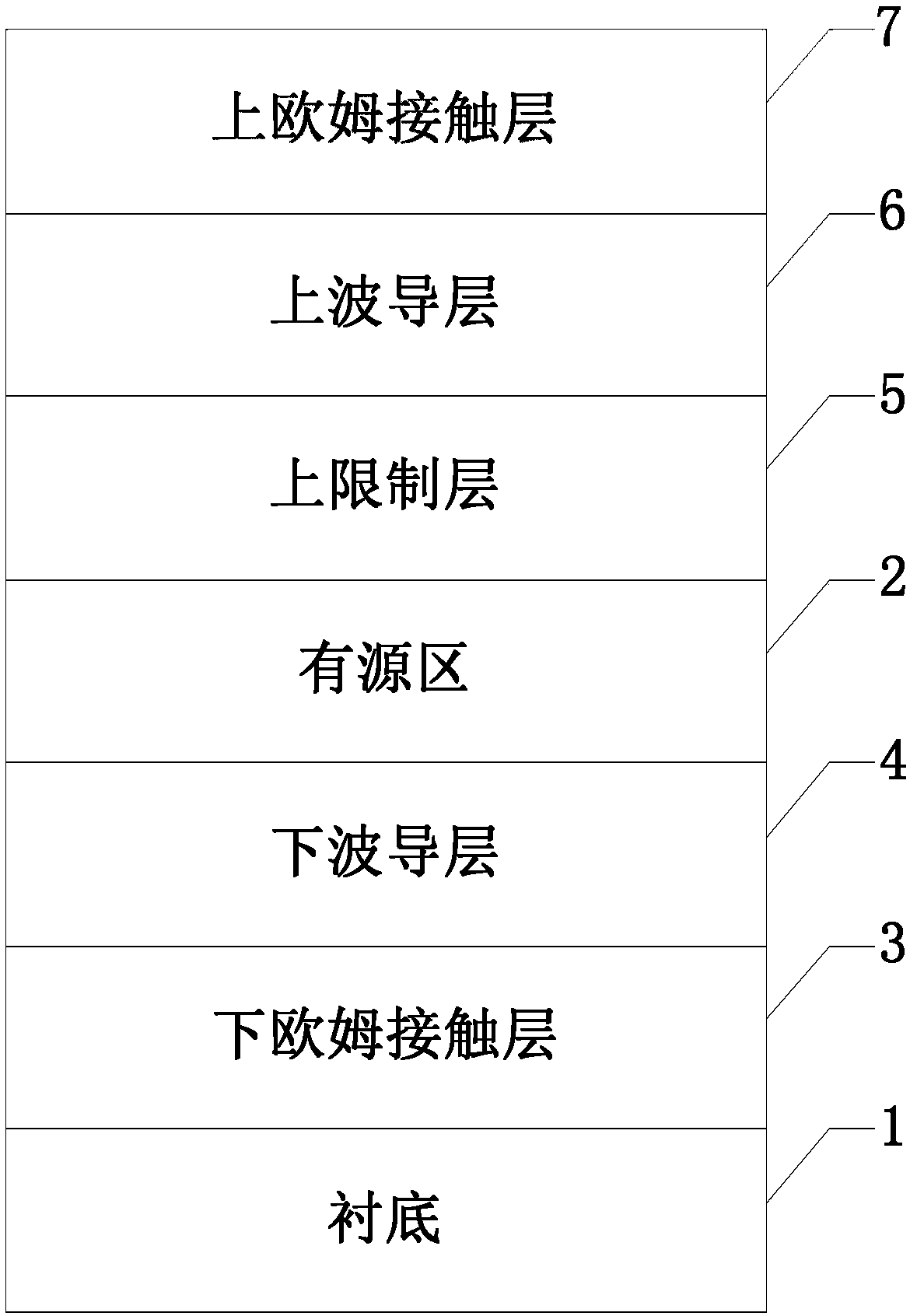
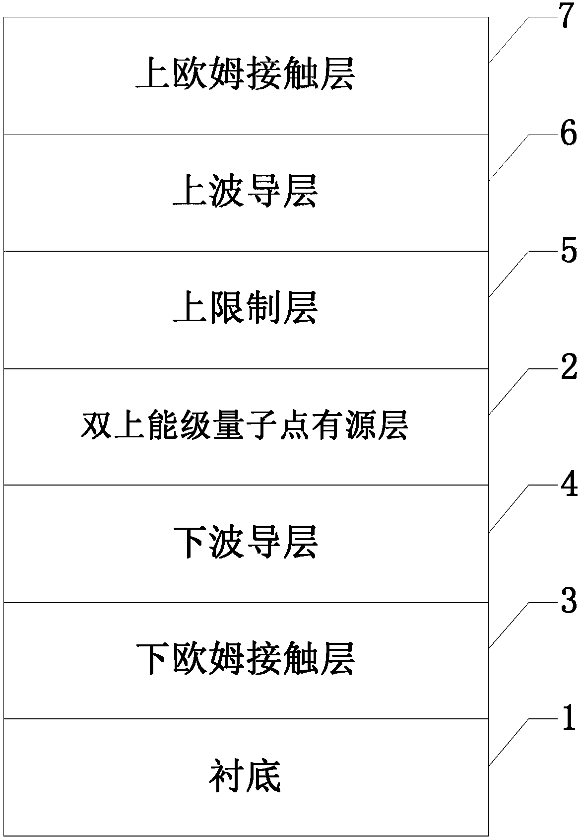
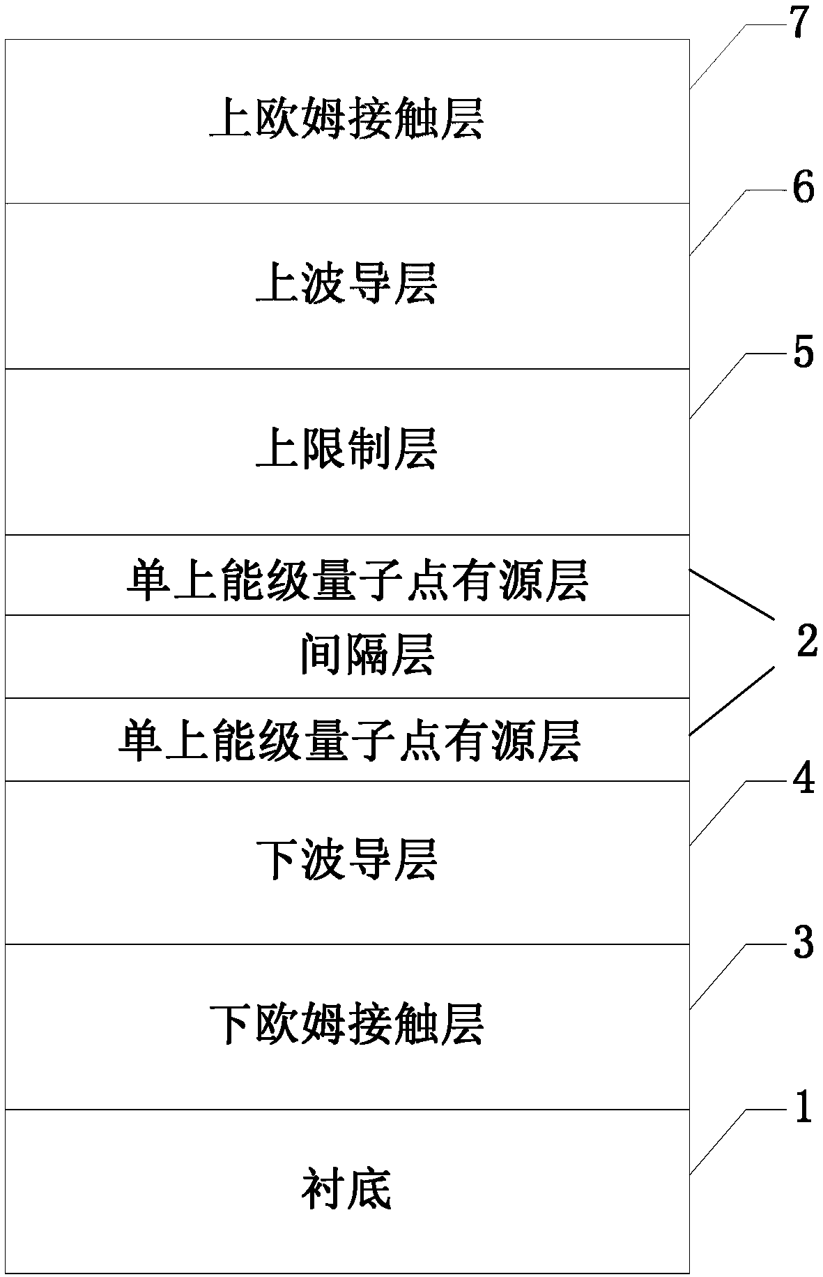
[0039] In the prior art, the widespread application of terahertz wave lasers has been hindered by the disadvantages of expensive equipment, large volume, high power consumption, non-continuously adjustable frequency, and inability to cover the entire terahertz wave band. In view of this, the present invention provides a A difference-frequency terahertz quantum cascade laser, by introducing a multi-period cascaded quantum dot active layer, based on the "phonon bottleneck" effect and non-uniform broadening of quantum dots, the performance of the difference-frequency terahertz quantum cascade laser is improved , such as power, conversion efficiency, tuning range, and threshold current density.

[0040] In order to make the object, technical solution and advantages of the present invention clearer, the present invention will be described in further detail below in conjunction with specific embodiments and with reference to the accompanying drawings.

[0041] figure 1 It is a sche...


PUM

PropertyMeasurementUnit
Thicknessaaaaaaaaaa
Thicknessaaaaaaaaaa
Thicknessaaaaaaaaaa

Abstract

The invention provides a difference frequency terahertz quantum cascade laser. The difference frequency terahertz quantum cascade laser comprises an active area, and the active area is located above asubstrate. The active area comprises multi-cycle bottom-up cascade quantum dot active layers, the quantum dot active layer in each cycle comprises a plurality of bottom-up InGaAs / InAlAs quantum well / barrier pairs and quantum dot insertion layers, one quantum dot insertion layer is inserted between every two InGaAs / InAlAs quantum well / barrier pairs, and each quantum dot insertion layer comprises astrain self-organized quantum dot InAs layer and a GaAs layer which is used for strain compensation. According to the difference frequency terahertz quantum cascade laser, the multi-cycle cascade quantum dot active layers are introduced, and based on the phonon bottleneck effect and the inhomogeneous broadening degree of quantum dots, the performance, such as power, conversion efficiency, tuningrange and threshold current density, of the difference frequency terahertz quantum cascade laser can be improved.

Description

technical field [0001] The invention relates to the technical field of infrared semiconductor optoelectronic devices, in particular to a difference-frequency terahertz quantum cascade laser. Background technique [0002] The terahertz THz band (30-300 μm) is between infrared and microwave, and the characteristic absorption peaks of many molecules are located in this band, which makes it have broad application prospects. For example, the collision frequency and plasma vibration frequency of many gas molecules at room temperature, and the rotation and vibration energy levels of many biological macromolecules are in the terahertz band, so important material information can be identified through terahertz spectroscopy, which is useful for drugs, explosives, etc. It can be used to detect and study the nonlinear dynamic process inside the substance; it can also be used for medical diagnosis through the unique response of biomolecules in this wave band. Moreover, THz waves have a ...

Claims


Application Information

Patent Timeline
IPC IPC(8): H01S5/343H01S5/34
CPCH01S5/3402H01S5/34333
Inventor 程凤敏张锦川刘峰奇卓宁王利军刘俊岐刘舒曼王占国
Owner INST OF SEMICONDUCTORS - CHINESE ACAD OF SCI
Why Eureka
Eureka Blog
Learn More