Power transmission system for electromobile power conversion and energy storage station
A technology for electric vehicles and power transmission systems, applied in electric vehicles, vehicle energy storage, charging stations for charging mobile devices, etc. The effect of efficient conversion and improved stability
- Summary
- Abstract
- Description
- Claims
- Application Information
AI Technical Summary
Problems solved by technology
Method used
Image

Examples
Embodiment 1
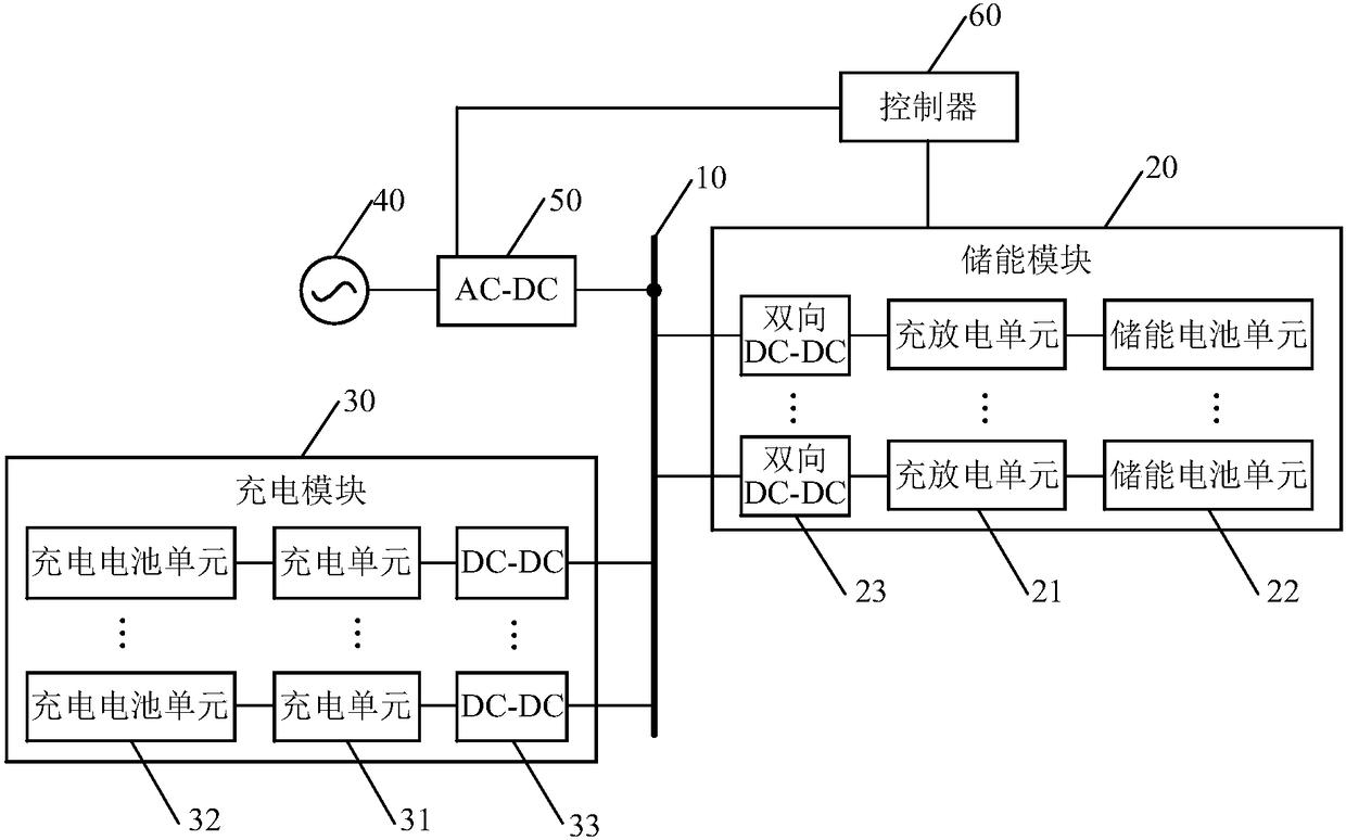
[0027] The controller 60 turns on the energy storage circuit by controlling the switching device (not shown in the figure) in the energy storage circuit (grid 40-bidirectional AC-DC conversion module 50-DC bus 10-bidirectional DC-DC conversion unit 23) to close circuit, the controller 60 sends control signals to the bidirectional AC-DC conversion module 50, the bidirectional DC-DC conversion unit 23 and the charging and discharging unit 21, respectively controlling the bidirectional AC-DC conversion module 50 to perform AC to DC conversion, and controlling the bidirectional DC- The DC converting unit 23 converts the high-voltage direct current to the low-voltage direct current, and controls the charging and discharging unit 21 to perform a charging operation, so that the energy storage battery unit 22 stores electric energy.
Embodiment 2
[0029] The controller 60 turns on the discharge circuit by controlling the switching device (not shown in the figure) in the discharge circuit (bidirectional DC-DC conversion unit 23-DC bus 10-bidirectional AC-DC conversion module 50-grid 40) to close, The controller 60 sends control signals to the bidirectional AC-DC conversion module 50, the bidirectional DC-DC conversion unit 23 and the charging and discharging unit 21, respectively controlling the bidirectional AC-DC conversion module 50 to perform DC to AC conversion, and controlling the bidirectional DC-DC conversion The unit 23 converts the low-voltage direct current to the high-voltage direct current, and controls the charging and discharging unit 21 to perform a discharging operation, and feeds back the electric energy stored in the energy storage battery unit 22 to the grid 40 .
[0030] In addition, in the above two implementation manners, the controller 60 can also control the switch device (not shown in the figure)...
Embodiment 3
[0032] During the valley power period when the electricity price is low, the controller 60 can control the switching device (not shown in the figure) in the energy storage circuit (grid 40-AC-DC conversion module 50-DC bus 10-bidirectional DC-DC conversion unit 23) shown) is closed to turn on the energy storage circuit, the controller 60 sends control signals to the AC-DC conversion module 50, the bidirectional DC-DC conversion unit 23 and the charging and discharging unit 21, respectively controlling the AC-DC conversion module 50 to perform AC to For direct current conversion, control the bidirectional DC-DC conversion unit 23 to perform conversion from high-voltage direct current to low-voltage direct current, and control the charging and discharging unit 21 to perform a charging operation, so that the energy storage battery unit 22 stores electric energy.
PUM
 Abstract
Description
Claims
Application Information
 - R&D
- Intellectual Property
- Life Sciences
- Materials
- Tech Scout
- Unparalleled Data Quality
- Higher Quality Content
- 60% Fewer Hallucinations
Browse by: Latest US Patents, China's latest patents, Technical Efficacy Thesaurus, Application Domain, Technology Topic, Popular Technical Reports.
© 2025 PatSnap. All rights reserved.Legal|Privacy policy|Modern Slavery Act Transparency Statement|Sitemap|About US| Contact US: help@patsnap.com