
Method for eliminating harmonic wave of radio frequency circuit and radio frequency circuit

A radio frequency circuit and harmonic frequency technology, applied in the field of communications, can solve the problems of harmonic interference signals having no effect, complex circuit structure, and inability to achieve harmonic elimination, so as to reduce the difficulty of digital processing, simplify circuit structure, reduce The effect of circuit cost

Active Publication Date: 2018-08-03
INST OF MICROELECTRONICS CHINESE ACAD OF SCI
View PDF6 Cites 6 Cited by
  • Summary
  • Abstract
  • Description
  • Claims
  • Application Information

AI Technical Summary

Problems solved by technology

If you want to use a filter to filter out harmonic interference signals, you need to divide it into multiple branches working in different frequency bands for gating filtering. Using multiple filter channels will take up too much volume and the circuit structure is complicated
However, the harmonic elimination circuit of active devices such as couplers cannot achieve harmonic elimination of any harmonic frequency in the working frequency band, and cannot be adjusted flexibly
At the same time, the existing baseband DPD technology can only eliminate intermodulation signal interference near the transmission signal bandwidth range, and has no effect on harmonic interference signals far beyond the feedback bandwidth range

Method used


Image

  • Method for eliminating harmonic wave of radio frequency circuit and radio frequency circuit
  • Method for eliminating harmonic wave of radio frequency circuit and radio frequency circuit
  • Method for eliminating harmonic wave of radio frequency circuit and radio frequency circuit

Examples


Embodiment

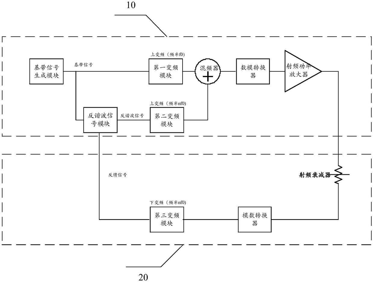
[0047] Please refer to figure 1 , The first embodiment of the present application provides a radio frequency circuit, including:

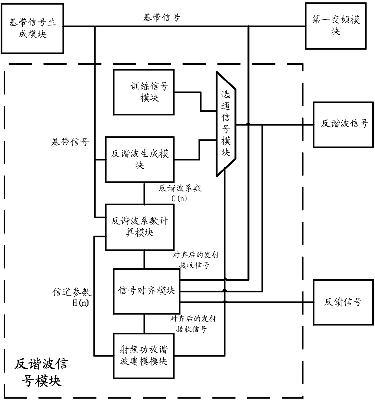
[0048] The transmitting branch 10 and the feedback branch 20, wherein the transmitting branch 10 includes a baseband signal generation module, a first frequency conversion module, a mixer, a digital-to-analog converter, a radio frequency power amplifier, an anti-harmonic signal module, and a second frequency conversion module , The baseband signal generation module is connected to the first frequency conversion module, the first frequency conversion module is connected to the mixer, the first end of the anti-harmonic signal module is connected to the baseband signal generation module, and the second end of the anti-harmonic signal module is connected to the second The frequency conversion module is connected, and the second frequency conversion module is connected to the mixer. The baseband signal generated by the baseband signal generation module is u...


PUM


Abstract

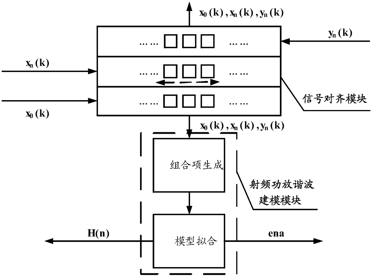
The invention discloses a method for eliminating a harmonic wave of a radio frequency circuit and a radio frequency circuit. The radio frequency circuit is of a structure that in a transmission branchcircuit, a baseband signal generated by a baseband signal generation module is input into a frequency mixer after being subjected to frequency conversion on a first frequency converter, after the baseband signal passes through an inverse harmonic signal module, an inverse harmonic signal is generated, the inverse harmonic signal is input into the frequency mixer after being subjected to frequencyconversion on a second frequency conversion module, the frequency mixer outputs a mixed signal after carrying out frequency mixing on the baseband signal subjected to frequency conversion and the inverse harmonic signal subjected to frequency conversion, and after the mixed signal passes through a digital-to-analog converter and a radio frequency power amplifier, a radio frequency signal is output; in a feedback branch circuit, the radio frequency signal output by the radio frequency power amplifier is subjected to down-conversion by a third frequency conversion module after being attenuatedby a radio frequency attenuator and converted by an analog-to-digital converter, and a feedback signal is output to the inverse harmonic signal module; and the inverse harmonic signal module calculates an inverse harmonic coefficient on the basis of a currently generated harmonic signal, the received baseband signal and the feedback signal, and generates an inverse harmonic signal on the basis ofthe inverse harmonic coefficient.

Description

Technical field [0001] The present invention relates to the field of communications, in particular to a method for eliminating harmonics of a radio frequency circuit and a radio frequency circuit. Background technique [0002] In the communication field, in order to increase the efficiency of the RF power amplifier, the RF power amplifier is often operated in a nonlinear region close to the saturation point. The transmitted signal will generate various interference signals due to the nonlinearity of the power amplifier. In addition to intermodulation interference signals near the original signal carrier frequency, harmonic interference signals with relatively large power are also generated at each harmonic frequency, causing spectrum pollution to interfere with other communications. channel. In order to suppress the non-linear interference of the RF power amplifier to other channels without reducing the output power of the RF power amplifier, the intermodulation interference of ...

Claims


Application Information

Patent Timeline
IPC IPC(8): H04B1/40H04L25/49
CPCH04B1/40H04L25/49
Inventor 彭玄邱昕慕福奇柴旭荣冷永清
Owner INST OF MICROELECTRONICS CHINESE ACAD OF SCI
Learn More