Primary blasting well forming method for middle guide well

A technology for pilot wells and detonating tubes is applied in the field of one-shot blasting of medium pilot wells, which can solve the problems of construction progress, difficult safety, low safety system, and many processing procedures, so as to enrich technologies and construction methods, reduce blasting costs, and reduce blasting costs. The effect of improving economic efficiency

Inactive Publication Date: 2018-08-07
浙江省隧道工程集团有限公司
View PDF7 Cites 13 Cited by
  • Summary
  • Abstract
  • Description
  • Claims
  • Application Information

AI Technical Summary

Problems solved by technology

During the construction process, due to the limitations of hydrogeological conditions and construction technology, the construction progress and safety are not easy to guarantee. Due to the small-section circular drilling and blasting construction, the safety risk is relatively large, there are many safety hazards, and there are many follow-up processing procedures, which are difficult, especially The safety system is low when workers work in the pilot well, and safety accidents are prone to occur

Method used


Image

  • Primary blasting well forming method for middle guide well

Examples


Embodiment 1

[0026] A kind of blasting well formation method of intermediate guide well, such as figure 1 shown, including the following steps:

[0027] (1) Measurement and positioning to determine the wellhead position of the shaft;

[0028] (2) Mechanical excavation at the shaft mouth: use excavators and picks to excavate the upper section of the shaft, clean up the site, level it, excavate the strong weathered layer, break it mechanically and clean it;

[0029] (3) Back digging at the bottom of the shaft: back digging at the bottom of the shaft for a cycle. The cycle refers to drilling, charging, connection, blasting and inspection after blasting. The height is 2.3m. Drilling, hole diameter 43mm, hole depth 2.3m, detonating tube connection, non-electric millisecond detonating detonator differential detonation;

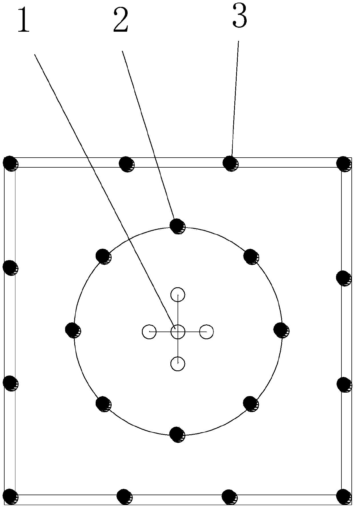
[0030] (4) Stakeout blasthole position according to the blasting design of the pilot shaft: use the total station to stake out the position of the pilot shaft in the 2m×2m ver...

Embodiment 2

[0039] With embodiment 1, difference is that in step (3), height 2m, hole depth 2m; The distance between the holes is 0.1m; then cut the hole 2, the diameter of the blast hole The distance between the holes is 0.4m; the peripheral hole 3 is finally drilled, and the diameter of the blast hole is Hole spacing 0.4.

Embodiment 3

[0041] With embodiment 1, difference is that in step (3), height 2.5m, hole depth 2.5m; The distance between the holes is 0.2m; then cut the hole 2, the diameter of the blast hole The distance between the holes is 0.6m; finally, the peripheral holes 3 are drilled, and the diameter of the blast hole is The hole distance is 0.6m.


PUM


Abstract

The invention relates to the field of tunnel engineering, and discloses a primary blasting well forming method for a middle guide well. The method includes the steps: (1) performing measuring and positioning to determine the wellhead position of a vertical well; (2) mechanically digging a wellhead of the vertical well; (3) reversely digging the bottom of the vertical well upwards; (4) according toa blasting design lofting blast hole position of the middle guide well: performing lofting to form 2m*2m middle guide well position of the vertical well by the aid of a total-station instrument, andlabeling the position of the blast hole position; (5) completely drilling a blast hole by a down-the-hole drill once; (6) plugging the bottom of the blast hole; (7) filling the blast hole with explosive; (8) plugging an upper opening of the blast hole with blast sludge after the blast hole is plugged by the explosive; (9) line connecting and explosion initiating, connecting starting detonators inthe blast holes in a clustering manner, and performing differential initiation of non-electric millisecond detonators. The method has the advantages that construction safety is improved, potential safety hazards are reduced, and life safety of construction staff is guaranteed.

Description

technical field [0001] The invention relates to the field of tunnel engineering, in particular to a method for forming an intermediate pilot well by one-time blasting. Background technique [0002] With the continuous improvement of our country's scientific and technological level and the continuous acceleration of urbanization, tunnel engineering has not only further developed in the direction of deeper, larger and more complex areas such as traditional mines, national defense, hydropower, and highways (railways). The construction of underground engineering often involves the construction of shaft structures, such as mine shafts, surge shafts of hydropower stations, public (railway) roads, underground parking lots, ventilation shafts of underground civil air defense projects, etc. In current engineering practice, the shaft excavation generally adopts the method of excavating the pilot shaft first, and then expanding the excavation. The construction of the intermediate pilo...

Claims


Application Information

Patent Timeline
Patent Type & Authority Applications(China)
IPC IPC(8): E21D1/03E21D3/00E21D1/00F42D3/04F42D1/00
CPCE21D1/03E21D1/00E21D3/00F42D1/00F42D3/04
Inventor 昌禄柱张恩山郭红里贺炳炎张宇江张春林陈水和费益滨
Owner 浙江省隧道工程集团有限公司
Why Eureka
Try Eureka