Printing paper tape lateral vibration testing device and testing method

A technology of lateral vibration and testing device, applied in the field of lateral vibration testing of paper tape and lateral vibration testing device of printed paper tape, can solve the problem that the testing device cannot work normally, single edge detection, center detection, line detection, detection lag, etc. problems, achieve flexible clock module configuration and interrupt function, realize human-computer interaction, and improve the effect of measurement accuracy

Active Publication Date: 2018-08-07
XIAN UNIV OF TECH
View PDF8 Cites 1 Cited by
  • Summary
  • Abstract
  • Description
  • Claims
  • Application Information

AI Technical Summary

Problems solved by technology

[0005] (1) Most of the existing devices use a single sensor, which can only detect one side of the paper tape. When the edge of the paper tape is damaged or irregularly changed, it is easy to cause detection errors; for the paper tape in a high-speed motion state, the system accuracy is low. Hysteresis in detection; when a single sensor fails, the test setup does not work properly;
[0006] (2) The roll paper has different specifications, and there are differences in the size of the web. The existing testing device can only realize a single edge detection, centering detection or line detection. Very complex and almost impossible to implement;
[0007] (3) During the printing process, the transparency, gloss, and chroma of different paper tapes are different. The existing testing device can only identify materials with a certain range of transparency. When the working range is exceeded, the device is difficult to detect normally;
[0008] (4) The working environment in the printing workshop is poor, and the existing devices mostly use traditional sensors, which are greatly affected by environmental factors and are sensitive to ambient light and noise, which may easily cause instability in the working state of the device

Method used


Image

  • Printing paper tape lateral vibration testing device and testing method
  • Printing paper tape lateral vibration testing device and testing method
  • Printing paper tape lateral vibration testing device and testing method

Examples


Embodiment Construction

[0046] The present invention will be described in detail below in conjunction with the accompanying drawings and specific embodiments.

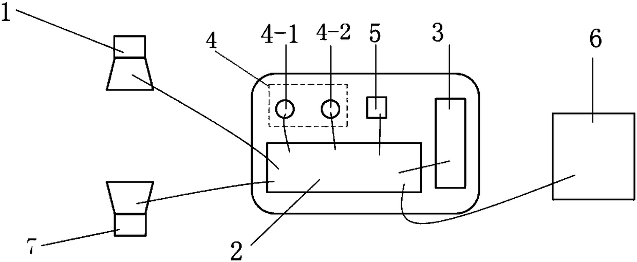
[0047] The invention provides a printing paper strip transverse vibration testing device, such as figure 1 As shown, it includes an upper ultrasonic sensor 1, a controller 2 and a centralized controller 6 connected in sequence, the controller 2 is also connected with a lower ultrasonic sensor 7, and the controller 2 is provided with a liquid crystal display 3, an indicator light unit 4, and an alarm 5 .

[0048] The models of the upper ultrasonic sensor 1 and the lower ultrasonic sensor 7 are the same, both

[0049] UNAR 18U6903 / S14G ultrasonic sensor.

[0050] Controller 2 is MSP430F149 single-chip microcomputer.

[0051] The liquid crystal display 3 is a 3.2-inch LCD1602 liquid crystal display.

[0052] The indicator light unit 4 includes a first indicator light 4-1 and a second indicator light 4-2. The model of the first indicator light ...


PUM


Abstract

The invention discloses a printing paper tape lateral vibration testing device comprising an upper ultrasonic sensor, a controller and a concentration controller connected in order; the controller isalso connected with a lower ultrasonic sensor; the controller is provided with a LCD, an indication lamp unit and an alarm. The printing paper tape lateral vibration testing device is stable in performance, reliable in operation, can accurately measure paper tape vibration displacements, and dual-probe detection can improve the system detection precision. The lateral vibration testing method can solve the roll web lateral vibration problems formed by machine vibrations in a high speed printing process, thus ensuring the paper table stable operation and accurate overprinting, improving productquality, reducing material waste, and obviously improving production efficiency.

Description

technical field [0001] The invention belongs to the technical field of printing equipment, and in particular relates to a printing paper tape transverse vibration test device, and also relates to a method for using the printing paper tape transverse vibration test device to carry out a paper tape transverse vibration test. Background technique [0002] With the continuous advancement of science and technology, the degree of mechanical automation has been greatly improved, and printing machinery and equipment are developing in the direction of high precision, high speed, high automation and multi-function. As the core equipment of modern commercial printing, books and magazines printing, and news publishing, the web printing machine performs uninterrupted printing, folding, binding, cutting and other printing processes in the form of continuous paper supply, with high efficiency and high quality printing. Good and other advantages. At present, the speed of the web book print...

Claims


Application Information

Patent Timeline
Patent Type & Authority Applications(China)
IPC IPC(8): G01H17/00G01M13/02
CPCG01H17/00G01M13/028
Inventor 侯和平邓瑞赵庆海徐卓飞赵颠颠
Owner XIAN UNIV OF TECH
Why Eureka
Try Eureka