Optical fiber wiredrawing technology

一种拉丝、工艺的技术,应用在制造工具、玻璃制造设备等方向,能够解决影响氦气冷却效应等问题,达到提高氦气冷却效果、提高导热效率、结构简单的效果

Active Publication Date: 2018-08-10
FUTONG GROUP CO LTD
View PDF4 Cites 2 Cited by
  • Summary
  • Abstract
  • Description
  • Claims
  • Application Information

AI Technical Summary

Problems solved by technology

[0017] The invention provides an optical fiber drawing process, which solves the defect that the existing optical fiber drawing process has a thick laminar bottom layer in the drawing cooling process and affects the cooling effect of helium

Method used


Image

  • Optical fiber wiredrawing technology
  • Optical fiber wiredrawing technology
  • Optical fiber wiredrawing technology

Examples


Embodiment 1

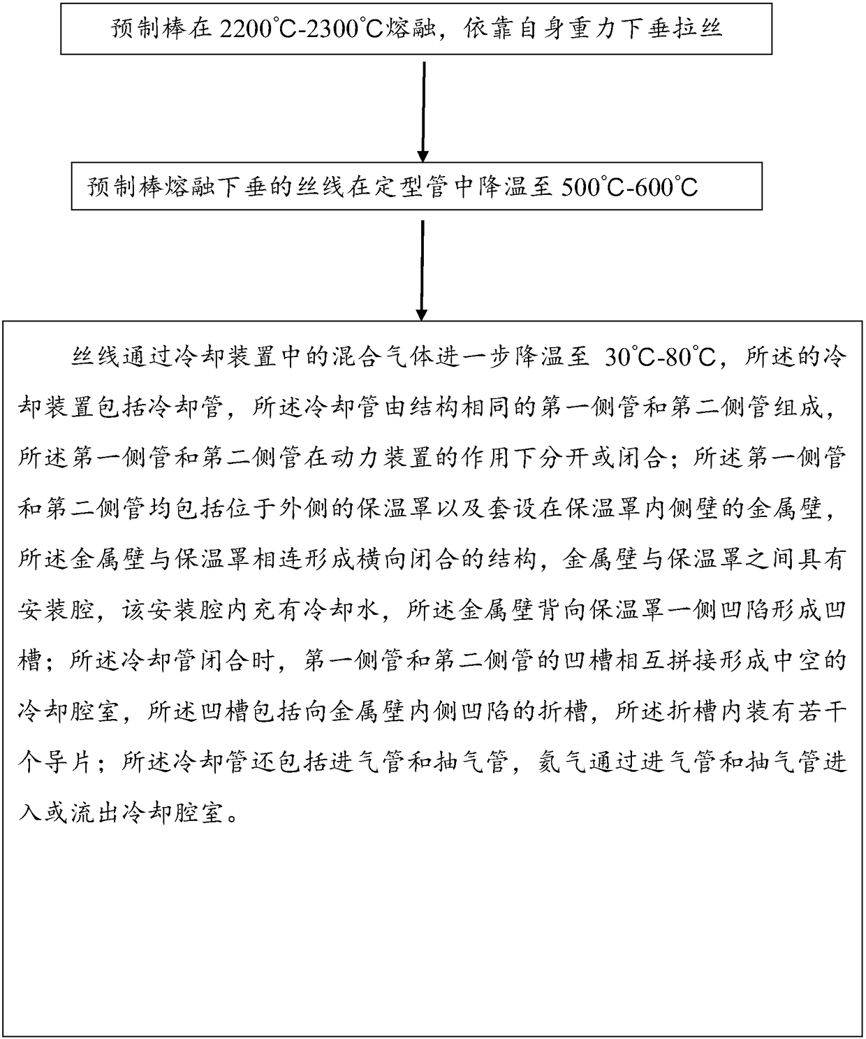
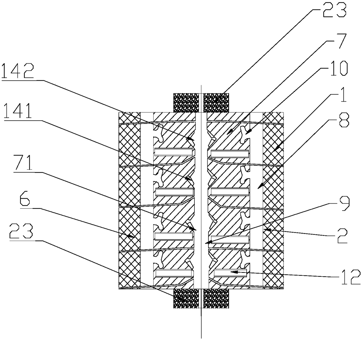
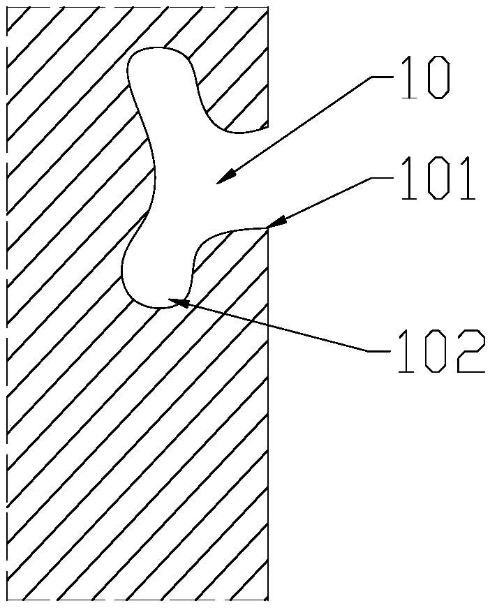
[0051] Embodiment 1: The embodiment of the present invention provides a cooling device 1 (see attached figure 2 , 3 , 4, 5, 6, 7), applied to step 3), the cooling device 1 cooling device includes a cooling pipe 2, and the cooling pipe is composed of a first side pipe 3 and a second side pipe 4 with the same structure , the first side pipe 3 and the second side pipe 4 are vertically separated or closed under the action of the power unit 5; The metal wall 7 on the inner side wall of the heat preservation cover 6, the metal wall 7 is connected with the heat preservation cover 6 to form a horizontally closed structure, and there is an installation cavity 8 between the metal wall 7 and the heat preservation cover 6, and the installation cavity 8 is filled with cooling water The side of the metal wall 7 facing away from the insulation cover 6 is recessed to form a groove 71; when the cooling pipe 2 is closed, the grooves 71 of the first side pipe 3 and the second side pipe 4 are s...

Embodiment 2

[0055] Embodiment 2: The temperature of the helium is 15°C. A drying device is installed at both ends of the cooling chamber. The drying device is equipped with a desiccant to effectively reduce the moisture in the cooling chamber. Under the condition that the temperature of the helium is controlled at 5°C-15°C, the condensation of the cooling water to The impact on the physical properties of the fiber on the fiber.

[0056] During the implementation of the embodiment of the present invention, helium gas at 5°C-15°C enters the cooling chamber through the intake pipe, and under the action of the groove and its folded grooves and guides, a turbulent flow is formed to destroy the optical fiber and bring it into the bottom layer of the air laminar flow, Helium is drawn out of the cooling chamber through the extraction tube. The drying device dries the air entering the cooling chamber to reduce the moisture entering the cooling chamber. The hot helium in the cooling chamber excha...


PUM

PropertyMeasurementUnit
diameteraaaaaaaaaa

Abstract

The invention discloses an optical fiber wiredrawing technology. The optical fiber wiredrawing technology comprises the following steps: 1) a melting and wiredrawing procedures: melting a preformed rod at 2200 DEG C to 2300 DEG C, drooping by self gravity and carrying out wiredrawing; 2) a shaping and cooling procedure: cooling melted and drooped wires of the preformed rod in a shaping pipe to 500to 600 DEG C; 3) a wiredrawing cooling procedure: further cooling the wires through helium gas in a cooling device to 30 DEG C to 80 DEG C, wherein the cooling device in step 3) comprises a cooling pipe, the cooling pipe is composed of a first side pipe and a second side pipe, which have the same structure, a mounting cavity is formed between a metal wall and a heat-insulation cover, the metal wall is concave in a direction opposite to the heat-insulation cover, the grooves of one pair of the side pipes are spliced to form a cooling chamber, each groove comprises a foldable groove and each foldable groove is internally provided with a guide blade. According to the optical fiber wiredrawing technology disclosed by the invention, the cooling chamber formed by structures including the grooves, the foldable grooves, the guide blades and the like is arranged, so that the turbulent flow is increased and the thickness of a laminar flow bottom layer formed by downward movement belts of optical fiber wires is effectively reduced, and furthermore, the helium gas cooling effect is improved.

Description

[0001] This application is a divisional application with an application date of April 12, 2016, an application number of 201610225135.7, and an invention title of "Optical Fiber Drawing Process". technical field [0002] The invention relates to the field of optical fiber production, in particular to an optical fiber drawing process. Background technique [0003] Optical fiber, short for optical fiber, is a fiber made of glass or plastic that acts as a means of light transmission. The optical fiber is composed of two layers of glass with different refractive indices. The inner layer is the optical core with a diameter of several microns to tens of microns, and the outer layer has a diameter of 0.1 to 0.2 mm. Generally, the refractive index of the inner core glass is 1% larger than that of the outer glass. According to the principle of refraction and total reflection of light, when the angle at which the light hits the interface between the inner core and the outer layer is ...

Claims


Application Information

Patent Timeline
Patent Type & Authority Applications(China)
IPC IPC(8): C03B37/025C03B37/027C03B37/03
CPCC03B37/025C03B37/027C03B37/02718C03B37/032
Inventor 王醒东
Owner FUTONG GROUP CO LTD
Why Eureka
Try Eureka