
Method and equipment for orientating crystal axis of in-plane anisotropic crystal

A technology of anisotropic and directional equipment, applied in the direction of polarization influence characteristics, etc., can solve the problems of strict application conditions, complex test process, low precision, etc., to achieve the effect of optimizing the optical path, realizing the measurement results, and reducing the overall volume

Active Publication Date: 2018-08-14
TIANJIN UNIV
View PDF6 Cites 2 Cited by
  • Summary
  • Abstract
  • Description
  • Claims
  • Application Information

AI Technical Summary

Problems solved by technology

[0004] However, in the process of implementing the present disclosure, the inventors of the present application found that the optical measurement methods in the prior art usually have disadvantages such as complicated test procedures, low precision, and strict applicable conditions.

Method used


Image

  • Method and equipment for orientating crystal axis of in-plane anisotropic crystal
  • Method and equipment for orientating crystal axis of in-plane anisotropic crystal
  • Method and equipment for orientating crystal axis of in-plane anisotropic crystal

Examples


Embodiment Construction

[0043] In the crystal axis orientation method and equipment for an in-plane anisotropic crystal provided by the embodiments of the present disclosure, reflection difference technology is used to determine the crystal axis direction, which not only improves the measurement accuracy, but also improves the scope of application of the method.

[0044] In order to make the purpose, technical solutions and advantages of the present disclosure clearer, the present disclosure will be further described in detail below in conjunction with specific embodiments and with reference to the accompanying drawings.

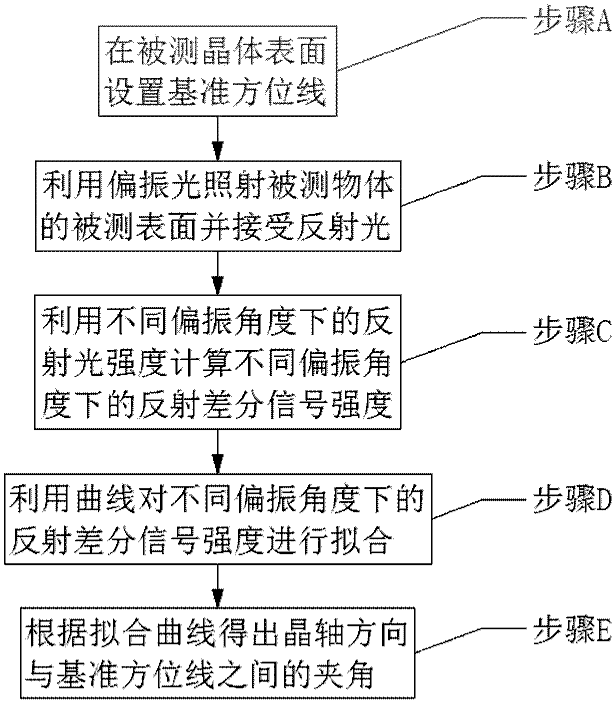
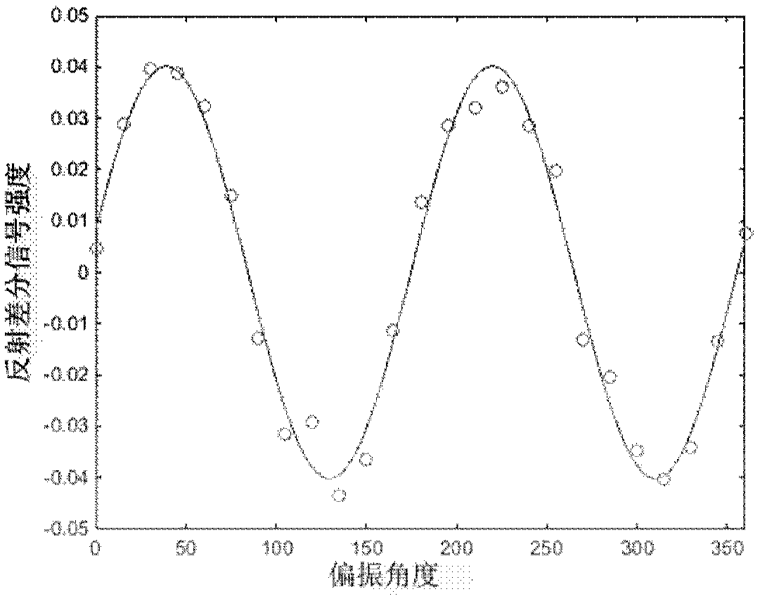
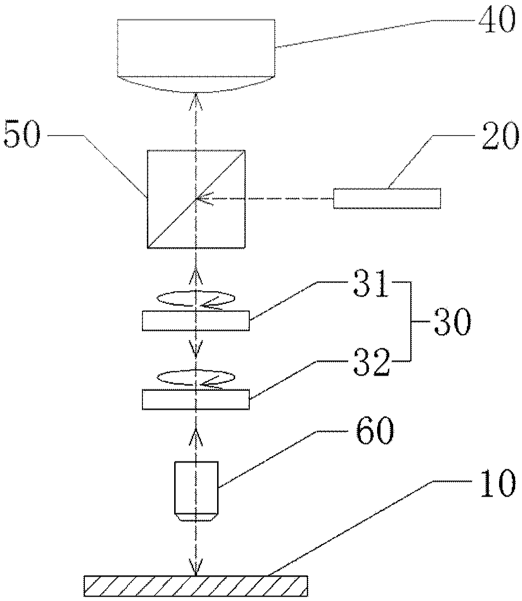
[0045] figure 1 It is a schematic diagram of the steps of the crystallographic axis orientation method of an in-plane anisotropic crystal according to an embodiment of the present disclosure. figure 2 It is a schematic diagram of the fitting curve in the crystallographic axis orientation method of the in-plane anisotropic crystal provided by the embodiment of the present disclosur...


PUM


Abstract

The invention provides a method and equipment for orientating a crystal axis of an in-plane anisotropic crystal. The method comprises the following steps: A, setting a reference azimuth line on a to be tested surface of a to be tested crystal; B, irradiating the to be tested surface of the to be tested crystal by utilizing polarized light and receiving reflected light; C, changing a polarization angle of the polarized light, and calculating the intensity of reflection differential signals at different polarization angles by utilizing the intensity of the reflected light at the different polarization angles; D, fitting the intensity of the reflection differential signals at the different polarization angles by utilizing a curve; and E, obtaining an included angle between a crystal axis direction and the reference azimuth line according to a fitted curve. The method and the equipment for orientating the crystal axis of the in-plane anisotropic crystal, which are provided by the invention, apply an optical reflection differential technology to determine the direction of the crystal axis, so that the technical problems of complex test flow, low precision and strict use conditions of acrystal axis orientating method in the prior art can be effectively solved.

Description

technical field [0001] The present disclosure relates to the technical field of surface optical characterization, in particular to a crystal axis orientation method and equipment for in-plane anisotropic crystals. Background technique [0002] Based on the three-dimensional periodicity in the spatial arrangement of the crystal structure, each crystal species can provide itself with a set of natural and reasonable crystal axis systems including three crystal axes. Due to the anisotropy of crystals, that is, the physical properties of crystals along different crystal directions are different, so the determination of the crystal axis direction is an important work in the process of crystal processing and semiconductor device fabrication. [0003] Crystal orientation methods fall into two broad categories, mechanical and optical. The mechanical method is usually very destructive to the crystal, so the optical method is generally used in the prior art to measure the direction of...

Claims


Application Information

Patent Timeline
IPC IPC(8): G01N21/21
CPCG01N21/21
Inventor 胡春光孙兆阳沈万福霍树春胡晓东胡小唐
Owner TIANJIN UNIV
Learn More