Broadband linear frequency modulation signal direction finding system and method based on time modulation

A linear frequency modulation signal, time modulation technology, applied in the modulation carrier system, FM carrier system, radio wave measurement system and other directions, can solve the problem of bandwidth modulation frequency limitation of incoming wave signal, and achieve the effect of saving cost and reducing complexity

Active Publication Date: 2018-08-17
SHANGHAI JIAO TONG UNIV
View PDF5 Cites 18 Cited by
  • Summary
  • Abstract
  • Description
  • Claims
  • Application Information

AI Technical Summary

Problems solved by technology

[0006] Aiming at the deficiencies in the prior art, the present invention provides a time-modulated broadband chirp signal direction-finding system and method. The system is a time-modulated antenna array system. The system and method use a radio frequency switch to The incoming wave signal is adaptively filtered in the tim

Method used


Image

  • Broadband linear frequency modulation signal direction finding system and method based on time modulation
  • Broadband linear frequency modulation signal direction finding system and method based on time modulation
  • Broadband linear frequency modulation signal direction finding system and method based on time modulation

Examples


Embodiment

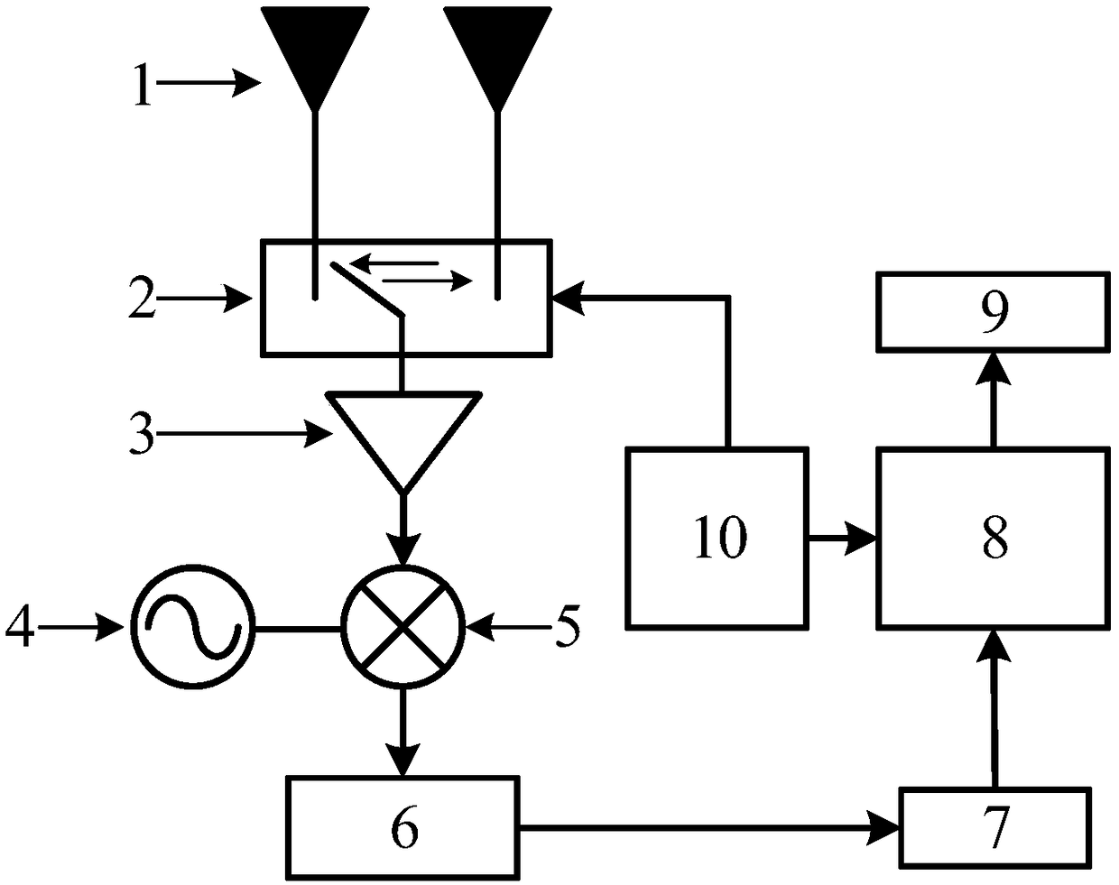
[0050] This embodiment provides a time modulation-based broadband chirp signal direction finding system, including an antenna array module, a radio frequency switch module, a radio frequency receiving channel module, a time-frequency signal processing module, an output display module, and a digital control module, wherein the radio frequency The channel module includes a low-noise amplifier 3 , a mixer 4 , a radio frequency local oscillator 5 , a low-pass filter 6 and an analog-to-digital converter 7 . The printed dipole antenna array unit 1 of the antenna array module is connected to a SPDT switch (high-speed radio frequency switch) 2 of the radio frequency switch module, and the SPDT switch is connected to a low-noise amplifier, and the low-noise amplifier connected with a mixer, the mixer is respectively connected with a radio frequency local oscillator and a low-pass filter, the low-pass filter is connected with an analog-to-digital converter, and the analog-to-digital conv...

example

[0063] Example, wideband chirp direction finding

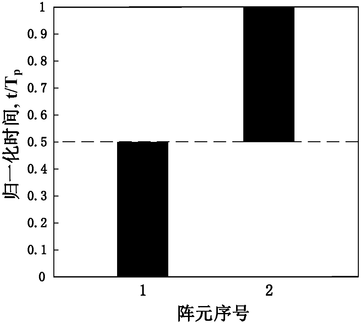
[0064] When the carrier frequency is f 0 =2GHz, the bandwidth is B=20MHz, and the chirp signal with the duration T=200μs is incident on the antenna array module at an azimuth angle of 15°, the said antenna array element spacing (ie array element spacing) d=λ / 2= 15cm, λ=c / f 0 is the wavelength of the incident signal, c is the propagation speed of the electromagnetic wave in the vacuum, and the periodic opening and closing timing diagram of the radio frequency switch module is shown in figure 2 shown, its modulation period is T p =1μs, modulation frequency f p =1MHz, in one modulation period, the on-time of each antenna array unit is 0.5μs, the number of sub-band signals divided by the entire chirp signal M=T / T p = 200.

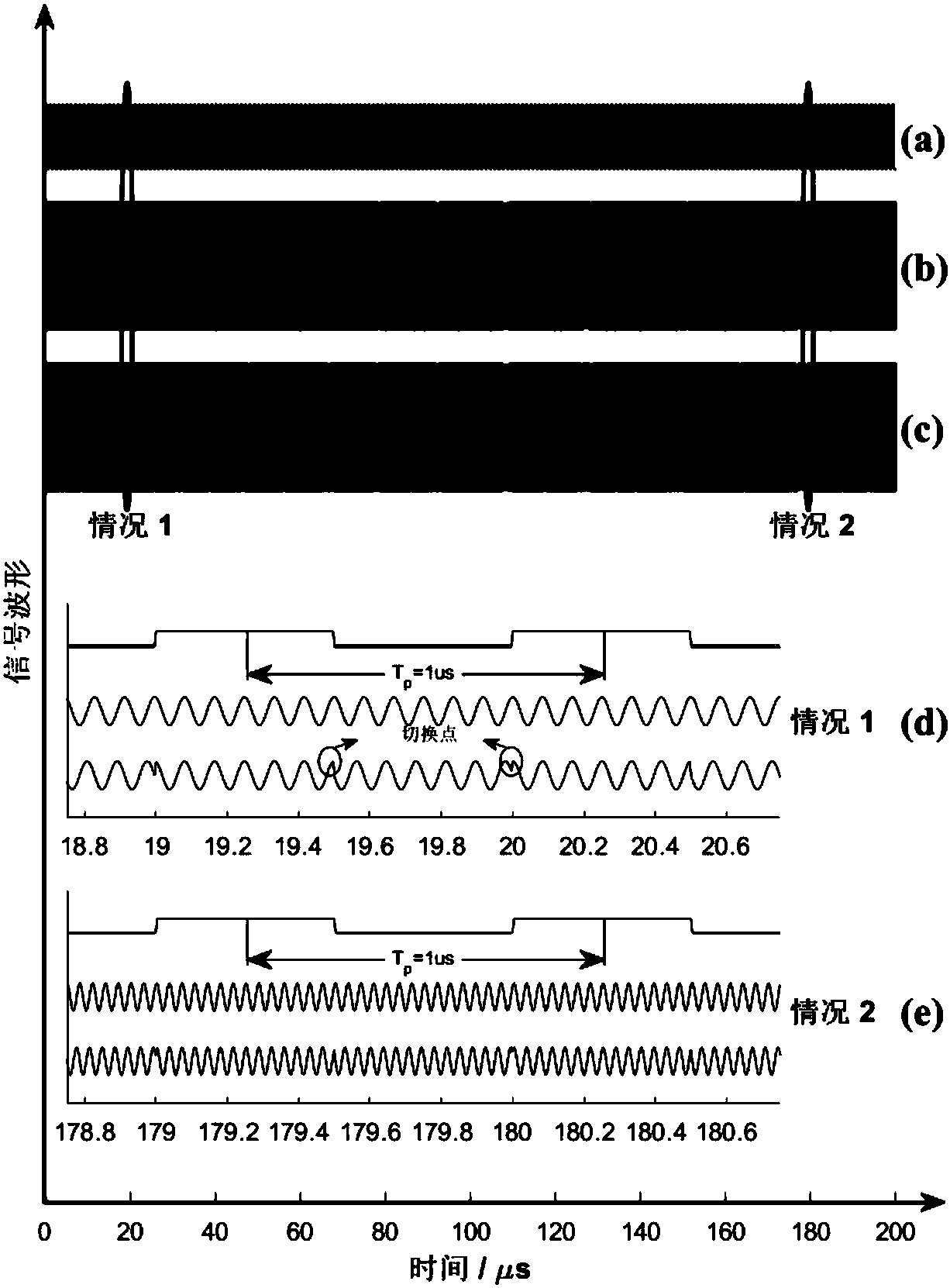
[0065] image 3 The time-domain waveforms of the modulated timing signal (a), the incident chirp signal (b) and the chirp signal modulated by the RF switch (c) are given, respectively, and in case 1: t=2...


PUM


Abstract

The invention provides a broadband linear frequency modulation signal direction finding system based on time modulation. An antenna array module is connected with a radio frequency switch module, theradio frequency switch module is connected with a radio frequency receiving channel module, the radio frequency receiving channel module is connected with a time-frequency signal processing module, the time-frequency signal processing module is connected with an output display module, and a digital control module is connected with the radio frequency switch module and the time-frequency signal processing module at the same time. The invention also provides a broadband linear frequency modulation signal direction finding method based on time modulation. The method aims to solve the direction finding problem of broadband linear frequency modulation signals in application of communication, radars and the like. Broadband incoming signals are filtered by the high-speed switching radio-frequencyswitch module and divided into a plurality of sub-band signals in a time domain, and the measurement of the incoming wave direction is realized by analyzing the time-frequency spectrum of each sub-band signal. The method has the advantages of being low in cost, simple in structure and low in algorithm complexity, and can be widely applied to the fields of broadband communication, electronic countermeasure and the like.

Description

technical field [0001] The invention belongs to the technical field of antenna engineering, in particular to a time modulation-based wideband linear frequency modulation signal direction finding system and method, which realizes the direction finding function of the wideband linear frequency modulation signal. Background technique [0002] Direction finding technology is widely used in radar, sonar and wireless communication. Traditional direction finding methods (amplitude ratio method, Doppler frequency shift method, time difference estimation and spatial spectrum estimation methods) exist or have complex hardware structures. , high cost, or complex calculation, or low estimation accuracy. [0003] After searching, it was found that the Chinese patent application with the application number: 201310317954.0 "Single-channel radio single-pass single-pass line electrical direction finding system" proposes a smart single-channel direction finding method, which uses a single-pol...

Claims


Application Information

Patent Timeline
IPC IPC(8): G01S3/46H04L27/10
CPCG01S3/465H04L27/103
Inventor 陈靖峰贺冲金荣洪耿军平梁仙灵朱卫仁
Owner SHANGHAI JIAO TONG UNIV
Why Eureka
Try Eureka