Coating method of fluorescent powder
A phosphor and coating technology, applied in electrical components, circuits, semiconductor devices, etc., can solve the problems of unqualified products, uneven phosphors, and inability of small particle powder to settle, so as to improve quality, yield, and improve safety effect
- Summary
- Abstract
- Description
- Claims
- Application Information
AI Technical Summary
Problems solved by technology
Method used
Image

Examples
Embodiment 1
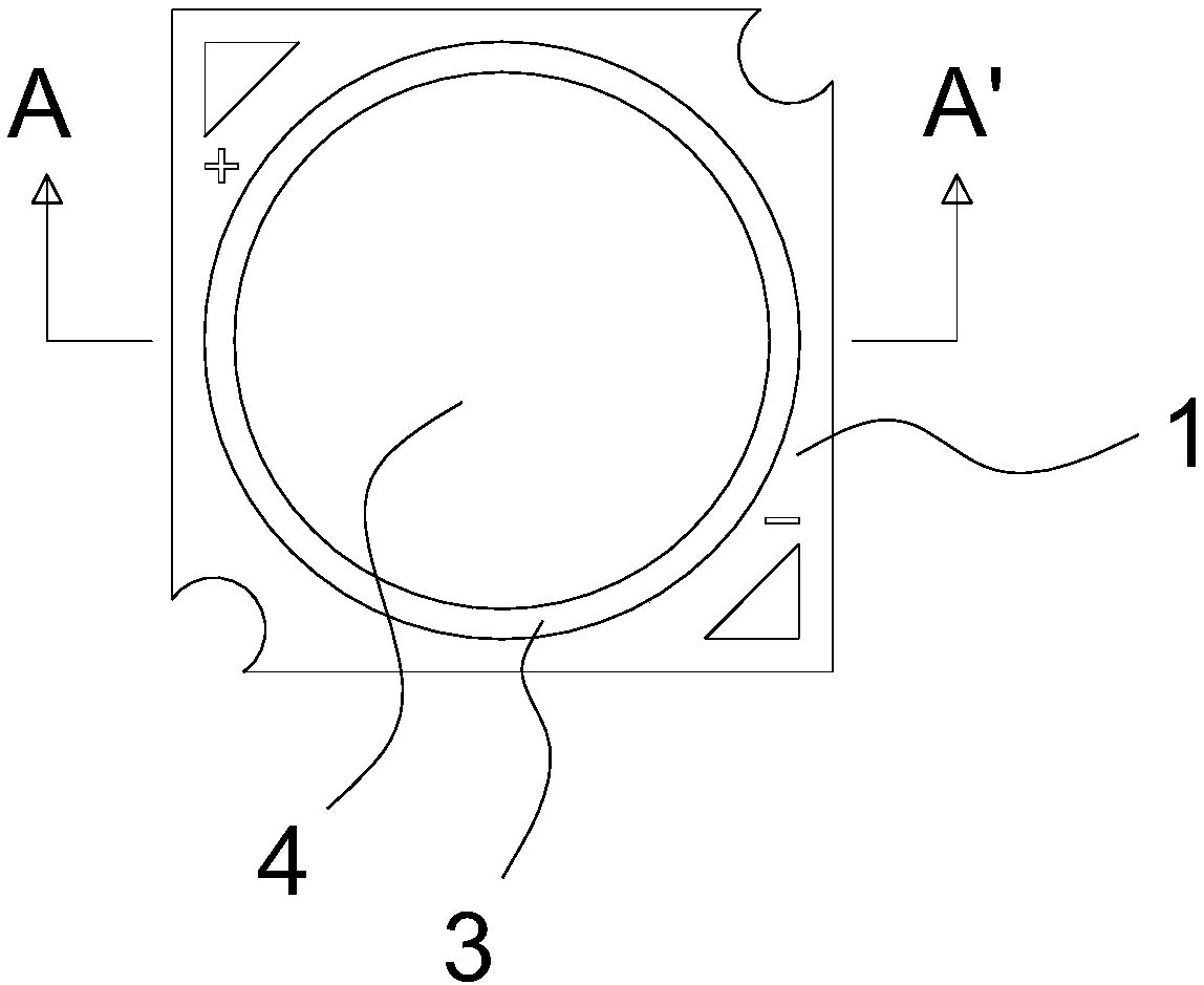
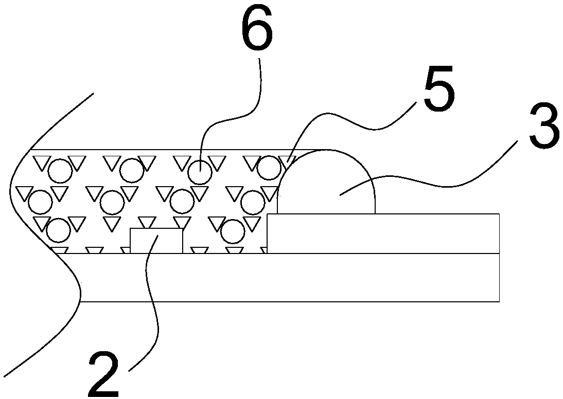
[0035] A phosphor coating method, such as image 3 As shown, after solid crystal and wire bonding, add magnetic particles 6 to the encapsulant 4 for dispensing, the phosphor powder 5 and magnetic particles 6 are randomly distributed in the encapsulant 4, and then the encapsulant 4 passes through the electromagnetic sedimentation device 7 to Make the magnetic particles 6 settle under the action of electromagnetic force; then carry out follow-up treatments such as curing.
[0036] Such as Figure 5 As shown, the magnetic particles 6 include a core 61 and a wrapping layer 62, the core 61 is made of iron, the diameter of the core 61 is 40-50nm, the wrapping layer 62 is a silicone rubber transparent wrapping layer 62, and the thickness of the wrapping layer 62 is 5 μm. -6 μm; the distribution concentration of the magnetic particles 6 in the packaging glue 4 is 0.3% of the weight of the packaging glue. The resistivity of the magnetic particles 6 is 20 Ω·m.
Embodiment 2
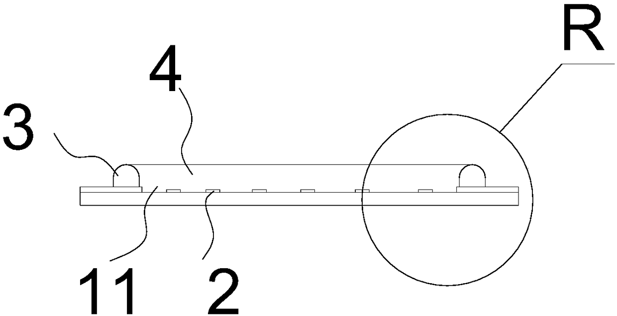
[0038] A phosphor coating method, such as Figure 4 As shown, dispensing is performed after solid crystal and wire bonding, and magnetic particles 6 are sprayed on the surface of the dispensed encapsulant 4, and the magnetic particles 6 are distributed on the surface of the encapsulant 4, and then the encapsulant 4 is passed through the electromagnetic sedimentation device 7 to Make the magnetic particles 6 settle under the action of electromagnetic force; then carry out follow-up treatments such as curing.
[0039] Such as Figure 5 As shown, the magnetic particle 6 includes an inner core 61 and a wrapping layer 62. The material of the inner core 61 is cobalt, and the diameter of the inner core 61 is 50-60 nm. The wrapping layer 62 is a silicone rubber transparent wrapping layer 62, and the thickness of the wrapping layer 62 is 4 μm. -5 μm; the distribution concentration of the magnetic particles 6 in the packaging glue 4 is 0.5% of the weight of the packaging glue. The res...
Embodiment 3
[0041] A phosphor coating method, such as Figure 4 As shown, after solid crystal and wire bonding, some magnetic particles 6 are added to the encapsulant 4 for dispensing, and some magnetic particles 6 are sprayed on the surface of the encapsulant 4 after dispensing, and the magnetic particles 6 are distributed on the surface and inside of the encapsulant 4 at the same time , and then make the encapsulating glue 4 pass through the electromagnetic sedimentation device 7, so that the magnetic particles 6 settle under the action of electromagnetic force; and then carry out follow-up treatments such as curing.
[0042] Such as Figure 5 As shown, the magnetic particle 6 includes a core 61 and a wrapping layer 62. The material of the core 61 is cobalt, and the diameter of the core 61 is 20-30nm. The wrapping layer 62 is a transparent wrapping layer 62 of silicon dioxide, and the thickness of the wrapping layer 62 is 6-8 μm; the distribution concentration of the magnetic particles...
PUM
| Property | Measurement | Unit |
|---|---|---|
| diameter | aaaaa | aaaaa |
| electrical resistivity | aaaaa | aaaaa |
| thickness | aaaaa | aaaaa |
Abstract
Description
Claims
Application Information
 - R&D
- Intellectual Property
- Life Sciences
- Materials
- Tech Scout
- Unparalleled Data Quality
- Higher Quality Content
- 60% Fewer Hallucinations
Browse by: Latest US Patents, China's latest patents, Technical Efficacy Thesaurus, Application Domain, Technology Topic, Popular Technical Reports.
© 2025 PatSnap. All rights reserved.Legal|Privacy policy|Modern Slavery Act Transparency Statement|Sitemap|About US| Contact US: help@patsnap.com