
Industrial energy-saving and emission-reducing type flue gas purification device

A technology for energy saving, emission reduction, and flue gas purification. It can be used in combination devices, separation devices, and gas treatment. It can solve the problems of reduced purification efficiency, no installation, leakage at pipe connections, etc., so as to increase air tightness and improve purification efficiency. , The effect of not easy to leak

Inactive Publication Date: 2018-08-21
浙江洲扬环保科技有限公司
View PDF1 Cites 2 Cited by
  • Summary
  • Abstract
  • Description
  • Claims
  • Application Information

AI Technical Summary

Problems solved by technology

[0004] The purpose of the present invention is to provide an industrial energy-saving and emission-reducing flue gas purification device to solve the problem that no corresponding water accumulation device is provided in the above-mentioned background technology, and the water body cannot fill the shell, so that the flue gas cannot fully react with the liquid. Reduce the purification efficiency, there is no device to increase the airtightness of the pipeline connection, and the pipeline connection is prone to leakage, causing environmental pollution problems

Method used


Image

  • Industrial energy-saving and emission-reducing type flue gas purification device
  • Industrial energy-saving and emission-reducing type flue gas purification device
  • Industrial energy-saving and emission-reducing type flue gas purification device

Examples


Embodiment Construction

[0018] The following will clearly and completely describe the technical solutions in the embodiments of the present invention with reference to the accompanying drawings in the embodiments of the present invention. Obviously, the described embodiments are only some, not all, embodiments of the present invention. Based on the embodiments of the present invention, all other embodiments obtained by persons of ordinary skill in the art without making creative efforts belong to the protection scope of the present invention.

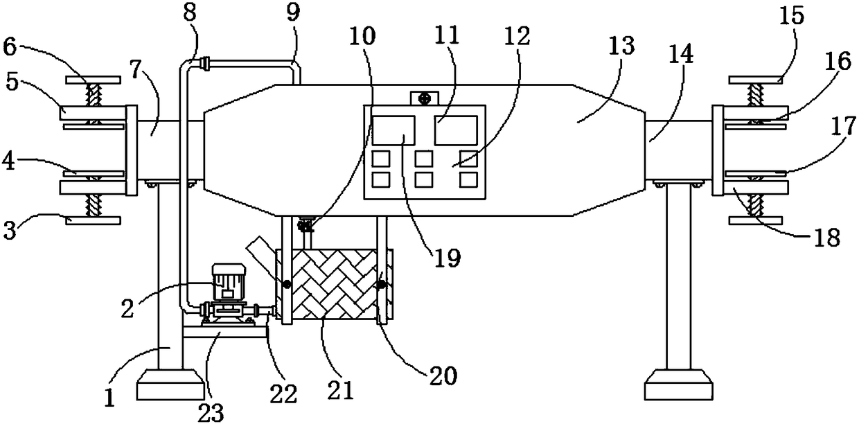
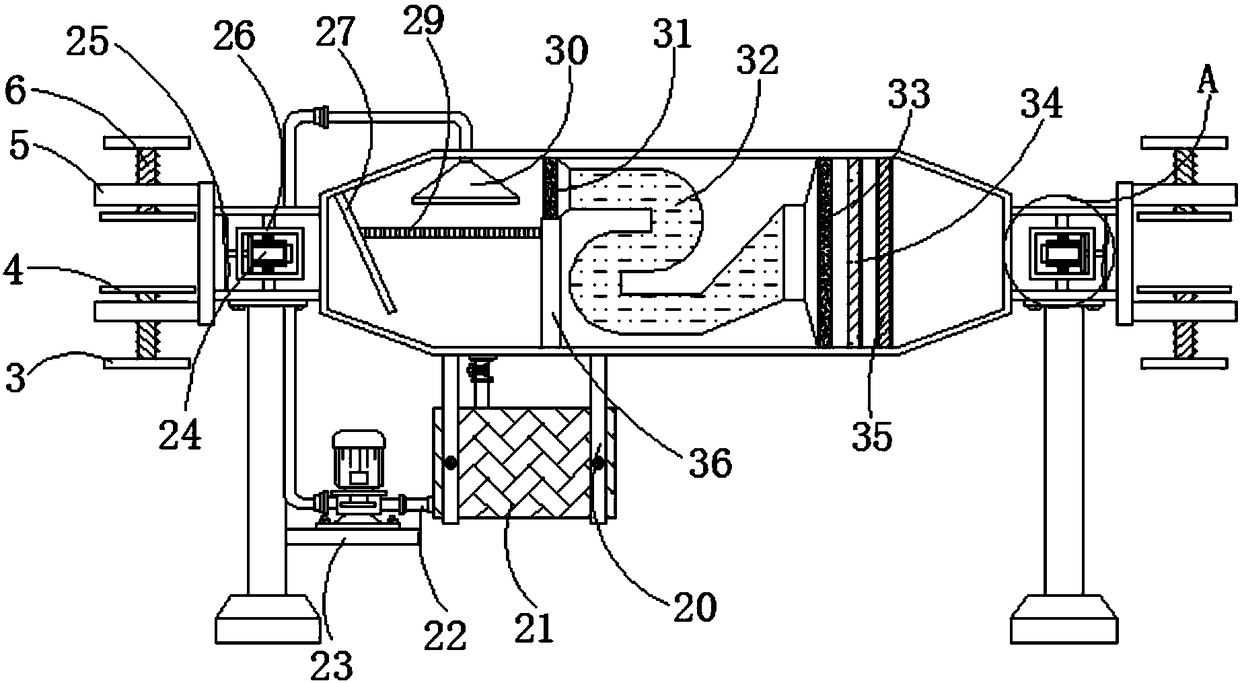
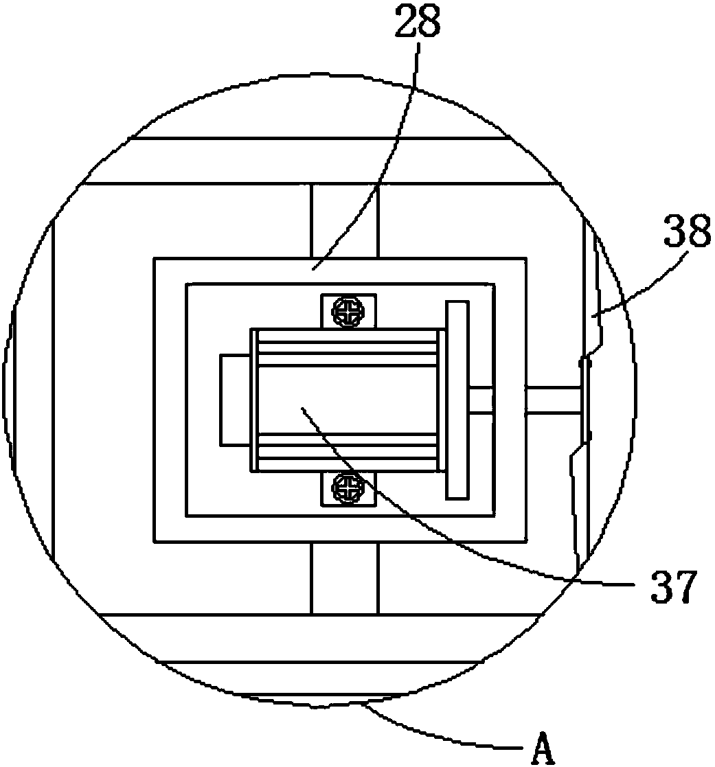
[0019] see Figure 1-Figure 4 , the present invention provides the following technical solutions: an industrial energy-saving and emission-reducing flue gas purification device, comprising a main body 13, a first pipe 7 is installed at one end of the main body 13, a second pipe 14 is installed at the other end, and the bottom of the first pipe 7 The support foot 1 is fixedly connected with the support foot 1, and a side plate 23 is installed on one side of the...


PUM


Abstract

The invention discloses an industrial energy-saving and emission-reducing type flue gas purification device which comprises a main body, wherein a first pipe is mounted at one end of the main body, and a second pipe is mounted at the other end of the main body; the bottom of the first pipe is fixedly connected with a supporting leg by a bolt; a side plate is mounted on one side of the supporting leg; the bottom of the side plate is fixedly connected with a circulating water pump by a bolt; a water inlet pipe is mounted at one end of the circulating water pump, and a U-shaped pipe is mounted atthe other end of the circulating water pump. The industrial energy-saving and emission-reducing type flue gas purification device is provided with the side plate, an atomizing water distributor, a partition plate and an electromagnetic valve; when a user needs to desulfurize flue gas, a PLC (Programmable Logic Controller) is used to close the electromagnetic valve, a water body is sprayed out bya pray nozzle and forms water mist by the atomizing water distributor; the water mist flows to the bottom of the main body to for a certain amount of accumulated water; the side plate prevents liquidfrom flowing out, so that the main body is filled with the water body, the flue gas can sufficiently react with the liquid, so as to improve the purification efficiency of the device.

Description

technical field [0001] The invention belongs to the technical field of flue gas purification devices, and in particular relates to an industrial energy saving and emission reduction type flue gas purification device. Background technique [0002] The flue gas purification device is a high-efficiency air purification device designed for industrial waste gas smoke and dust. The air purification system is widely used in machinery, hardware, electronic appliances, optoelectronics, chemicals, tobacco, pharmaceuticals, food, biology and other industries and other places polluted by smoke, dust and dust. [0003] In the Chinese patent No. 201720865819.3, a biomass fuel boiler flue gas purification device is disclosed. When the traditional purification device is in operation, the flue gas flow is upward from the bottom of the tower through the fan, and the desulfurization liquid is sprayed. Spray downwards, but during the interweaving contact process of flue gas and spray liquid, b...

Claims


Application Information

Patent Timeline
IPC IPC(8): B01D53/78B01D53/50B01D53/86B01D50/00B01D46/30B01D46/00
CPCB01D53/78B01D46/0036B01D46/30B01D50/00B01D53/50B01D53/8603B01D2247/102B01D2258/0283
Inventor 周勇定
Owner 浙江洲扬环保科技有限公司
Learn More