Device for feeding rod with lifting head

A technology for feeding devices and rods, which is applied in transportation and packaging, metal processing, metal processing equipment, etc., can solve the problems of reducing the detection accuracy of pressure sensors, low positioning accuracy, and low probability of material suction, so as to overcome the decline in positioning accuracy , High probability of inhalation and long service life

Active Publication Date: 2018-08-21
无锡丹尼克尔自动化科技有限公司
View PDF11 Cites 4 Cited by
  • Summary
  • Abstract
  • Description
  • Claims
  • Application Information

AI Technical Summary

Problems solved by technology

[0004] 1. The scope of application is narrow, and miniature bars with hanging heads, especially those with larger hanging heads, are prone to reverse attraction; threaded screws often cannot enter the suction hole with the correct posture, which affects the take-out mechanism to take nails;
[0005] 2. The materials are easy to concentrate and accumulate. Driven by the rotation of the separation plate, the materials are concentrated from the lowest position to the upper area of ​​the rotation direction, resulting in too little material at the lowest position, resulting in a low probability of material suction;
[0006] 3. The mechanical wear of the intermittent rotation drive mechanism is relatively large, and the positioning accuracy is getting lower and lower with the increase of the wear degree, which affects the accurate nail removal of the take-out mechanism; in addition, the positioning of the intermittent rotation drive mechanism is prone to deviation, which affects the take-out mechanism to take nails
[0007] 4. The same air path used by the suction hole for confirmation of the highest position and the suction hole near the lowest position is likely to block the vacuum generator in the air path due to dirt in the material, reduce the detection accuracy of the pressure sensor, and affect the belt head Normal operation of the bar feeding device

Method used


Image

  • Device for feeding rod with lifting head
  • Device for feeding rod with lifting head
  • Device for feeding rod with lifting head

Examples


Embodiment 1

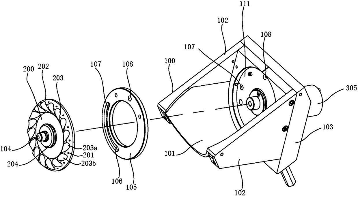
[0038] Such as Figures 1 to 8 As shown, the rod feeding device with suspension head includes a hopper 100 with an opening upward, a rotating shaft 104 vertically rotatably connected to the side wall of the hopper 100, a turntable 200 located in the hopper 100 and coaxially connected with the rotating shaft, and a The driving mechanism 300 that drives the shaft to rotate outside the hopper 104; the hopper 100 includes an arc panel 101, a side plate 102, and a mounting plate 103 with an arc-shaped bottom. An annular sealing ring 105, an annular groove 111 for fitting the annular sealing ring 105 is arranged on the mounting plate, and at least An arc groove 106, in the arc groove 106, is provided with several suction holes 107 through the annular sealing ring 105 and the mounting plate 103; There is a through confirmation suction hole 108; the outer peripheral surface of the turntable 200 is evenly distributed in the circumferential direction with a plurality of suction holes 2...

Embodiment 2

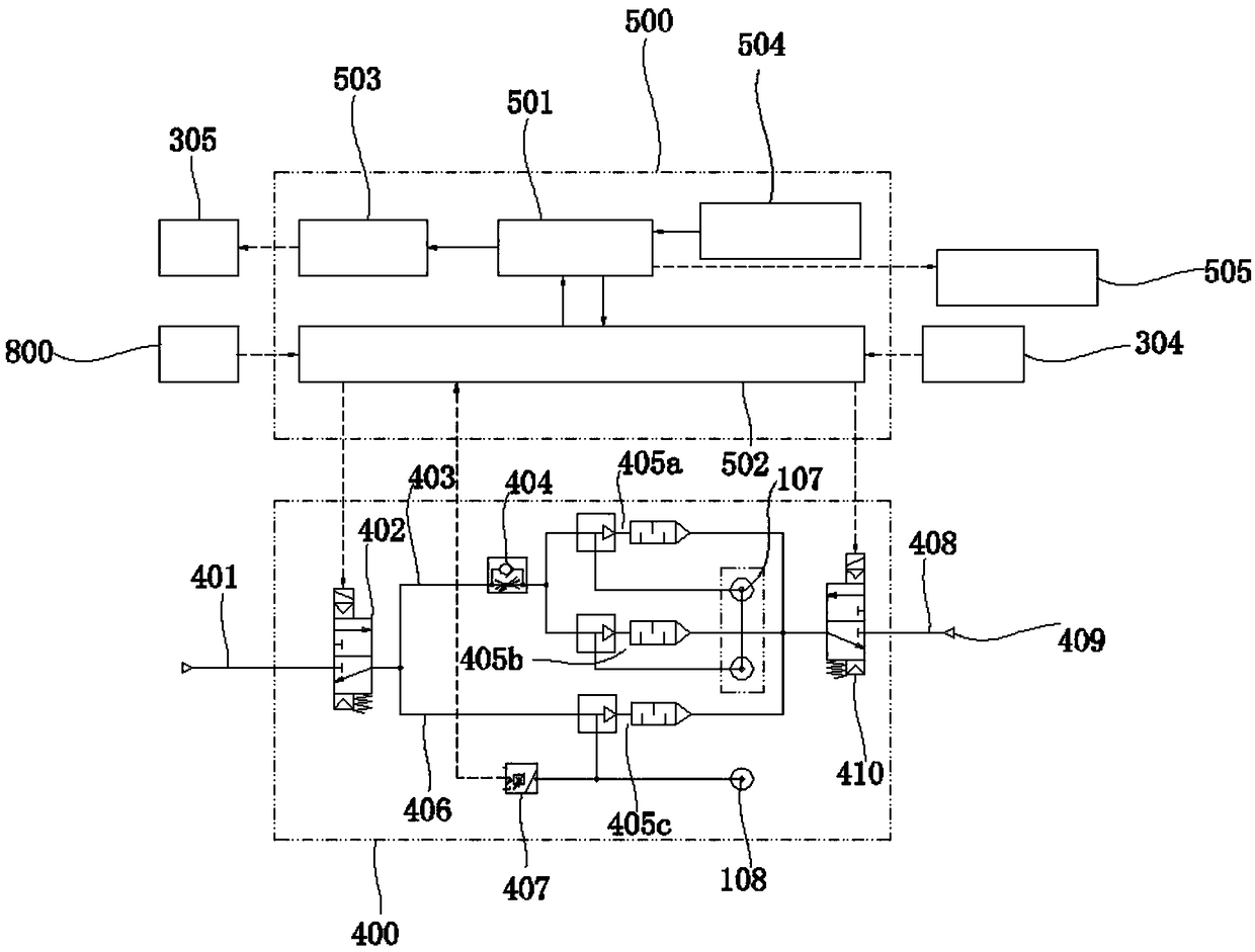
[0051] In Embodiment 1, after confirming that the position surface sensor 304 detects the position of the lever 303, the signal is sent to the control unit 500, and then the control unit gives the signal to the corresponding mechanism, such as the take-out mechanism 800 and the motor 305, and there are devices The reaction time is short, and the motor 305 cannot suddenly stop after detecting the position signal of the lever, so that the dial 302 and the sheave 301 may miss the best fitting position when the take-out mechanism operates. Embodiment 1 is suitable for low-speed drive feeding.

[0052] Embodiment 2 On the basis of Embodiment 1, a driving mechanism suitable for high-speed drive feeding is provided, which can respond quickly and adjust the relative positions of the dial, the dial lever and the sheave.

[0053] Such as Figure 9 As shown, the drive mechanism 300 includes a sheave 301, a dial 302, a lever 303, a motor 305, and a sensor 304b for confirming a position; ...

Embodiment 3

[0055] On the basis of Embodiment 1 or 2, Embodiment 3 provides an embodiment of a preferred material shifting mechanism.

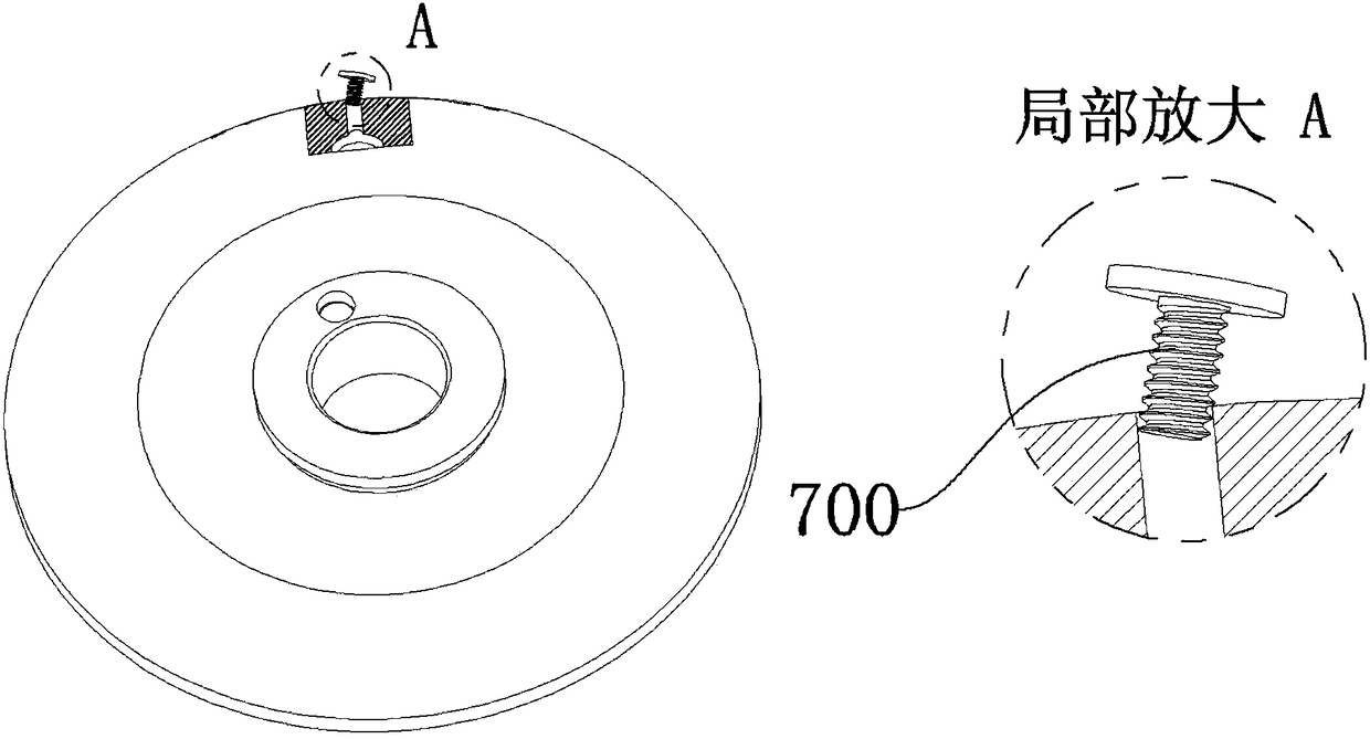
[0056]As shown in 10, an installation hole is provided on the installation plate 103 between the arc groove 106 inside the hopper 100 and the confirmation suction hole 108, and the dialing mechanism 600a is installed. The dialing mechanism 600a includes a mounting block 601a, a fixing screw 602a, a spring 603a, shifting lever shaft 604a and shifting claw 605a; the upper surface of the mounting block 601a is provided with a shifting rod shaft hole, and the shifting rod shaft is connected with the shifting claw with fixing screws, and the lower surface of the mounting block 601a is provided with a T-shaped groove, and a T-shaped groove A spring 603a and a lever shaft 604a are installed vertically inside.

[0057] Similarly, the mounting plate 103 on the outside of the hopper 100 is provided with a lever shaft hole and a T-shaped groove penetrating to the in...


PUM


Abstract

The invention discloses a device for feeding a rod with a lifting head. The device comprises a hopper, a rotating disc and a driving mechanism, wherein a rotating shaft for connecting the rotating disc and the driving mechanism is arranged on the mounting plate of the hopper; the mounting plate is provided with an annular sealing ring on the inner side of the hopper; an arc-shaped groove is formedin the bottom of the annular sealing ring; gas sucking holes are formed in the arc-shaped groove and the mounting plate in a communicating manner; a confirmation gas sucking hole is formed in the topof the annular sealing ring; material sucking holes communicated with the gas sucking holes and the confirmation gas sucking hole in a one to one correspondence manner are formed in the rotating disc. The device is characterized in that a shifting groove is formed in the rotating disc; the material sucking holes are stepped holes; the gas sucking holes and the confirmation gas sucking hole are connected with a gas source pipeline; the driving mechanism is a geneva wheel driving mechanism of which the center distance can be adjusted; the gas source pipeline and the driving mechanism are electrically connected with a control unit; a shifting mechanism is arranged inside the hopper. The device has the advantages that a plurality types of rods with lifting heads can be fed into the material sucking holes with a high probability at correct postures, are retained in the material sucking holes, and are further accurately positioned and conveyed to a discharge position.

Description

technical field [0001] The invention belongs to the technical field of material conveying, and in particular relates to a method of sucking and holding the rods with hanging heads such as screws and rivets in the suction holes provided on the turntable, and transporting the bars with hanging heads to the predetermined take-out through the rotation of the turntable. The position is used for the feeding device of the take-out mechanism to take the nails. Background technique [0002] In the electronics industry, the assembly of screws has developed from the traditional manual tightening to the current automatic screw machine technology, and the work efficiency has been improved by hundreds of times. The automatic screw machine includes a screw arrangement machine, a screw alignment machine, a screw feeder, etc. The main function is to transport the screws to the predetermined removal position. In the prior art, automatic screw machines are generally divided into vibration dis...

Claims


Application Information

Patent Timeline
Patent Type & Authority Applications(China)
IPC IPC(8): B65G47/91B23P19/00B23P19/06
CPCB23P19/001B23P19/06B65G47/915B65G47/917
Inventor 汪洋王剑坤
Owner 无锡丹尼克尔自动化科技有限公司
Why Eureka
Try Eureka