
Deep in-situ in-hole shearing testing system and testing method thereof

A testing system and internal shearing technology, applied in the direction of using stable shear force to test material strength, using stable tension/pressure to test material strength, etc., can solve the problem that the shear rate and readings have great influence and affect the test results. Accuracy, borehole wall collapse, etc., to achieve the effect of good integrity and stability, accurate and reliable test data, and improve quality and efficiency.

Pending Publication Date: 2018-08-21
CHINA RAILWAY DESIGN GRP CO LTD +1
View PDF9 Cites 9 Cited by
  • Summary
  • Abstract
  • Description
  • Claims
  • Application Information

AI Technical Summary

Problems solved by technology

Among them, the BST in-situ soil in-hole shear tester produced by Handy Company of the United States has no normal and shear deformation test system, and cannot obtain the stress-strain relationship curves under normal stress at all levels, so it can only obtain The peak shear strength under normal stress and the corresponding cohesion and internal friction angle, and the equipment is driven by hand gear and manual reading, the shear rate and reading are greatly affected by human factors, which is time-consuming and laborious
In the PHICOMETRE in-situ drilling shear test system produced by French APAGEO company and the in-situ soil in-hole shear test device disclosed in the invention patent publication number CN104458445A, the shear head is a cylinder, and the length of the shear head is more than 20 cm , not suitable for thinner stratum tests with a thickness of less than 30cm, and manual hydraulic jacks are used, which is difficult to control a constant shear rate and affects the accuracy of test results; the in-situ shearing and The static load tester adopts the disk shearing soil formed by the pendulum supported by the support bar. This mechanical control cannot ensure that the pendulum is evenly opened, and there may be local shearing of the surrounding soil, and it is impossible to obtain reliable results. The test data, and when encountering medium and strong weathered residual soil, the broken rock block is likely to jam the support rod, resulting in the failure of the test
[0005] In addition, when the above-mentioned types of in-situ shearing equipment are used for in-situ testing in deep formations, drilling rigs are required to cooperate with opening holes, and frequent loading and unloading of probe rods and lifting of drills are required, which greatly affects the integrity and stability of the borehole wall. Stability, which in turn affects the accuracy of the subsequent in-hole shear test results, and may easily cause the wall of the drilled hole to collapse. The in-situ shear probe buried in the hole cannot be taken out, which brings great difficulties to the deep in-situ shear test. Great risk and safety hazard

Method used


Image

  • Deep in-situ in-hole shearing testing system and testing method thereof
  • Deep in-situ in-hole shearing testing system and testing method thereof
  • Deep in-situ in-hole shearing testing system and testing method thereof

Examples


Embodiment Construction

[0061] The deep in-situ in-hole shear test system and its test method of the present invention will be described in detail below with reference to the accompanying drawings.

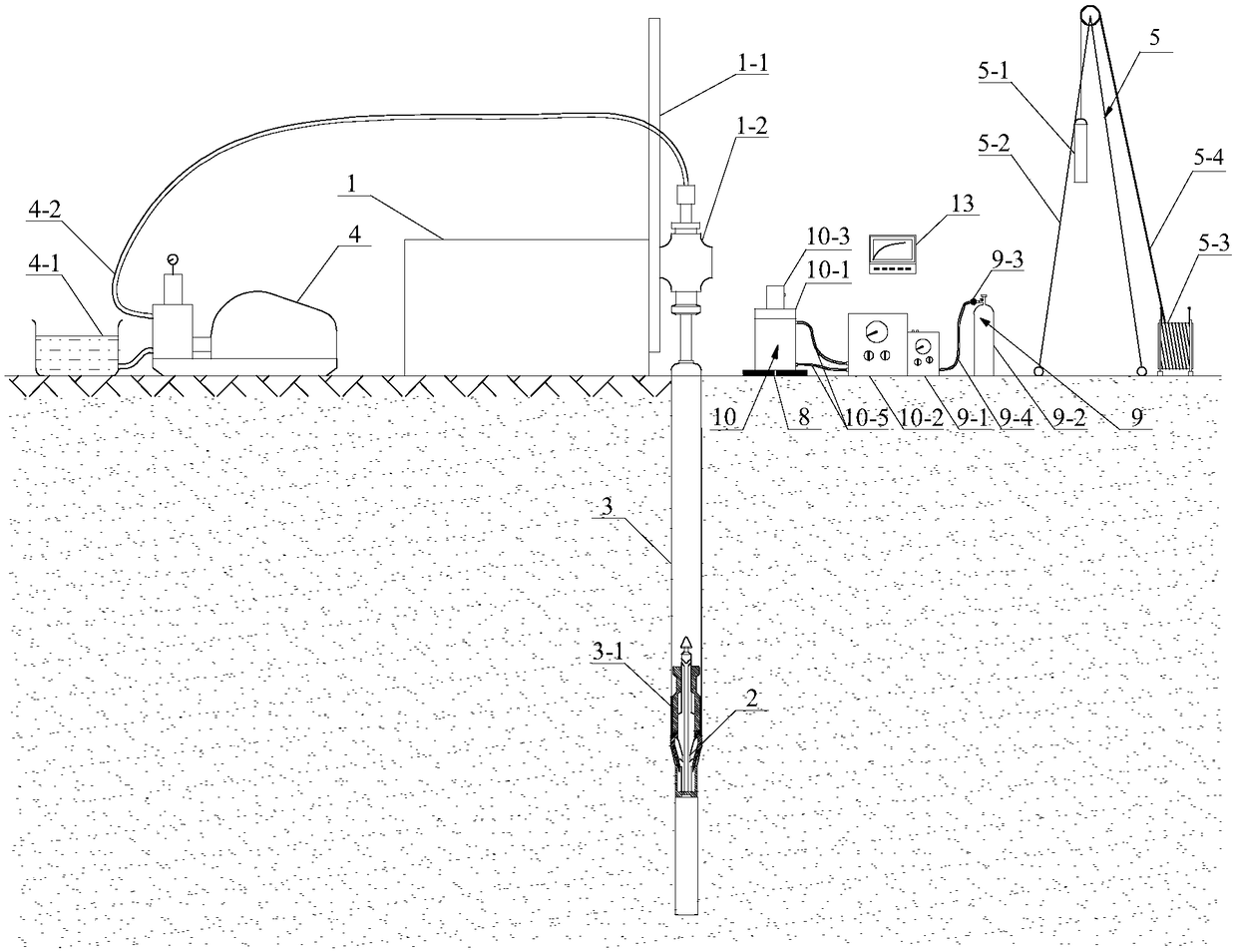
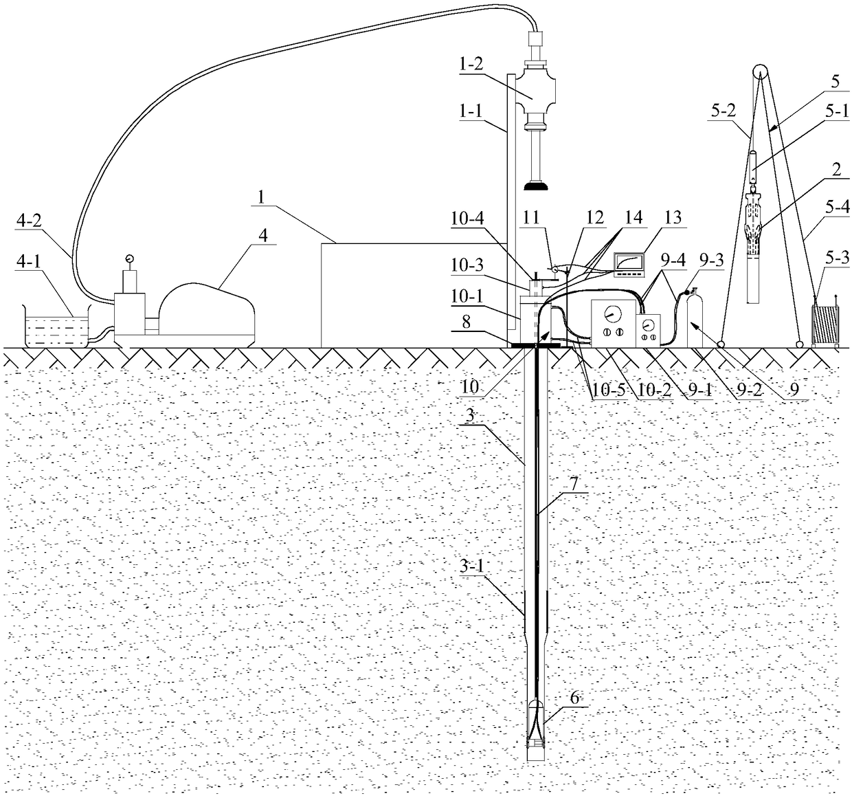
[0062] Such as figure 1 and figure 2 As shown, the deep in-situ in-hole shear test system of the present invention includes: a drilling rig 1, a tensioned casing core drilling tool, a casing 3, a mud pump 4, a drilling tool fishing device 5, a shear probe 6, and a pull rod 7. Reaction base plate 8, normal stress load measurement device 9, shear stress load measurement device 10, dial indicator 11, magnetic meter frame 12, data acquisition recorder 13 and data cable 14.

[0063] The drilling rig 1 includes a drilling tower 1-1 and a power head 1-2, which are used to drive the casing 3 and the positioning end pipe 3-1 at the bottom of the casing 3 to drill into the formation. The positioning end pipe 3-1 is used to drive the tensioned casing core drilling tool 2 for drilling and sampling. After drilling...


PUM


Abstract

The invention discloses a deep in-situ in-hole shearing testing system, which comprises a drilling machine, an expanding-converging type sleeve core drill bit, a sleeve, a mud pump, a drilling tool fishing device, a shearing probe, a pull bar, a normal stress loading and measuring device, a shearing force loading and measuring device, a micrometer gauge, and a data collection recorder. The drilling machine drives the sleeve to go into a stratum; a positioning end pipe drives the expanding-converging type sleeve core drill bit to carry out drilling and sampling; the drilling tool fishing deviceis used to lift the expanding-converging type sleeve core drill bit from the sleeve; the pull bar delivers the shearing probe to a predetermined test depth; the normal stress loading and measuring device applies a normal stress on the shearing probe; the shearing force loading and measuring device is used to lift the shearing probe; the micrometer gauge measures the shearing deformation amount oftested soil sheared by the shearing probe; and the data collection recorder records the time-varying shearing deformation and shearing force during the lifting process of the shearing probe. The system has the advantages of simple structure and convenient operation and is capable of obviously improving the quality and efficiency of a deep in-situ in-hole shearing test.

Description

technical field [0001] The invention belongs to the field of geotechnical engineering in-situ testing, in particular to a deep in-situ shear testing system and a testing method thereof. Background technique [0002] Cohesion and internal friction angle are important shear strength indicators of soil, and are important parameters for calculation of earth pressure and foundation bearing capacity, analysis of embankment, slope, foundation pit, tunnel stability and design of their supporting structures. At present, cohesion and internal friction angle are mainly measured by drilling and taking soil samples for indoor tests. The indoor test methods used include direct shear test and triaxial compression test. The indoor test measurement method greatly disturbs the soil. After the soil sample is unloaded by stress release and reloaded by the indoor test, there must be differences between the shear strength index of the soil and the in-situ shear strength index on site, and the tes...

Claims


Application Information

Patent Timeline
Patent Type & Authority Applications(China)
IPC IPC(8): G01N3/24G01N3/12
CPCG01N3/12G01N3/24
Inventor 李鹏李国和陈新军刘振田
Owner CHINA RAILWAY DESIGN GRP CO LTD
Learn More