
Manufacturing method of carbon fiber composite material centrifuge rotor

A centrifuge rotor and composite material technology, which is applied in the field of carbon fiber composite centrifuge rotor production, can solve the problems of failure to manufacture carbon fiber rotor products, radial cracking of rotor products, low rated speed, etc., and achieve light structure and easy use. Effect of long life and increased rated speed

Inactive Publication Date: 2018-08-24
CHANGSHA HIGH & NEW TECH INDAL DEV ZONE XIANGYI CENTRIFUGE INSTR +1
View PDF3 Cites 3 Cited by
  • Summary
  • Abstract
  • Description
  • Claims
  • Application Information

AI Technical Summary

Problems solved by technology

Due to various reasons such as structural design and immature manufacturing process, this kind of rotor failed to give full play to the advantages of carbon fiber, and showed defects such as radial cracking, axial delamination, and low rated speed of the rotor product. Manufacture truly practical and commercialized carbon fiber rotor products

Method used

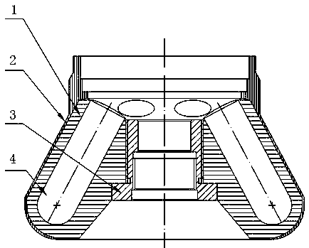

Image

  • Manufacturing method of carbon fiber composite material centrifuge rotor
  • Manufacturing method of carbon fiber composite material centrifuge rotor
  • Manufacturing method of carbon fiber composite material centrifuge rotor

Examples


Embodiment 1

[0037] Step 1. Use T300 grade carbon fiber unidirectional prepreg fabric with carbon fibers arranged in one direction in one direction as the raw material, and impregnate it with resin. The tensile strength of the fiber is 3800MPa, the tensile modulus of elasticity is 230MPa, and the resin is epoxy resin (or Phenolic resin), content 28%, prepreg thickness 0.15mm.

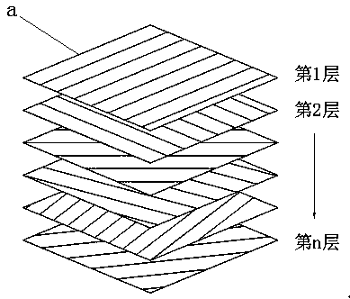
[0038] Step 2. Cut sheet a of the same size, such as 500mm×500mm, on the carbon fiber unidirectional prepreg at 0°, ±15°, ±30°, ±60°, and 90°, totaling 700 pieces, such as figure 2 shown; and then lay these carbon fiber unidirectional prepreg sheets a layer by layer to form a laminate, so that the fiber arrangement direction of each layer of prepreg in the laminate is distributed in the direction of 360 degrees, as shown in image 3 shown.

[0039] Step 3. Move the laminate to the middle of the two heating panels of the hot press, heat and press the laminate to form and solidify. The curing temperature, time and p...

Embodiment 2

[0045] Step 1. Use T700 grade carbon fiber unidirectional prepreg cloth with carbon fibers arranged in one direction in one direction as the raw material, and impregnate it with resin. The tensile strength of the fiber is 4700MPa, the tensile modulus of elasticity is 235MPa, and the resin is epoxy resin (or Bismaleimide resin), content 33%, prepreg thickness 0.25mm.

[0046] Step 2. Cut sheet a of the same size, such as 600mm×600mm, on the carbon fiber unidirectional prepreg at 0°, ±11.25°, ±22.5°, ±45°, and 90°, totaling 900 pieces, such as figure 2shown; and then lay these carbon fiber unidirectional prepreg sheets a layer by layer to form a laminate, so that the fiber arrangement direction of each layer of prepreg in the laminate is distributed in the direction of 360 degrees, as shown in image 3 shown.

[0047] Step 3. Move the laminate to the middle of the two heating panels of the hot press, heat and press the laminate to form and solidify. The curing temperature, tim...


PUM

PropertyMeasurementUnit
tensile strengthaaaaaaaaaa

Abstract

The invention discloses a manufacturing method of a carbon fiber composite material centrifuge rotor. The manufacturing method comprises the following steps that carbon fiber unidirectional prepreg cloth with carbon fiber arranged in one direction in an unidirectional mode is used as a raw material, and the carbon fiber unidirectional prepreg cloth is impregnated with resin; a plurality of piecesof carbon fiber unidirectional prepreg cloth are laid and stacked into a laminated layer layer by layer, and the fiber arrangement direction of each layer of prepreg cloth in the laminated layer is enabled to be distributed in the direction of 360 degrees; the laminated layer is moved to the position between two heating panels of a hot press, and is heated and pressurized to be formed and cured, then a carbon fiber laminated board with a two-dimensional structure is obtained, and is cut to machine a cylindrical core body blank, carbon fiber bundles are used for being wound around the peripheryof a rotor core body, then the rotor core body is heated and cured in a drying oven to obtain a core body reinforcing body, and then the outer contour of the core body reinforcing body is machined, so that a carbon fiber rotor body with a designed outer shape and a three-dimensional structure is formed. The centrifuge rotor manufactured by the method has the advantages of being more reasonable indesign, higher in rotating speed and strength and the like.

Description

technical field [0001] The invention belongs to a manufacturing method of a centrifuge rotor, in particular to a manufacturing method of a carbon fiber composite material centrifuge rotor. Background technique [0002] The rotors traditionally used in high-speed or ultra-high-speed centrifuges are generally made of aluminum alloy or titanium alloy, which are heavy, not resistant to corrosion, low in strength, and prone to metal fatigue due to cyclic loads. With the continuous increase of the speed of the centrifuge and the increasingly harsh medium environment used, aluminum and titanium materials can no longer fully meet the requirements. And carbon fiber has the characteristics of high strength, light weight, corrosion resistance, and no metal fatigue. This material that was originally limited to aerospace use is gradually being used to make centrifuge rotors. For example, Chinese patent document CN101829637A discloses a centrifuge The carbon fiber rotor, its main product...

Claims


Application Information

Patent Timeline
Patent Type & Authority Applications(China)
IPC IPC(8): B29C70/34B29C65/48B29C65/64B29C53/60
Inventor 文寄槐刘文慧武育荣
Owner CHANGSHA HIGH & NEW TECH INDAL DEV ZONE XIANGYI CENTRIFUGE INSTR
Learn More