Sealing pyrolyzing furnace achieving continuous feeding and discharging

A pyrolysis furnace, feeding and discharging technology, applied in coking ovens, special forms of dry distillation, petroleum industry, etc., can solve the problems of poor sealing effect, low thermal efficiency, low pyrolysis efficiency, etc., and achieve good promotion and application value, structure Reasonable design and high pyrolysis efficiency

Pending Publication Date: 2018-08-24
湖北春阳环保装备有限公司
View PDF1 Cites 4 Cited by
  • Summary
  • Abstract
  • Description
  • Claims
  • Application Information

AI Technical Summary

Problems solved by technology

[0003] Existing organic waste pyrolysis furnaces and corresponding pyrolysis methods usually have the following deficiencies: 1) The material cannot be continuously fed in and out. Usually, after the feeding of a furnace is completed, it is sealed and then pyrolyzed. After the material is discharged, it is repeated. Specifically, a kind of garbage carbonization pyrolysis furnace disclosed in CN 201505660 has the disadvantages of feeding and discharging at intervals, poor continuity, high labor intensity and low pyrolysis efficiency; 2) it can realize continuous feeding and discharging to a certain extent, but In terms of structural design, there are still low thermal efficiency (the heating plate heats the material on the endless belt), poor stability of feeding and discharging materials (the double-layer slide valve controls the feeding and discharging materials), poor sealing effect, and materials during pyrolysis in the furnace Conveyor equipment (ring belt) is damaged quickly by heat, resulting in high cost and many other shortcomings

Method used


Image

  • Sealing pyrolyzing furnace achieving continuous feeding and discharging
  • Sealing pyrolyzing furnace achieving continuous feeding and discharging
  • Sealing pyrolyzing furnace achieving continuous feeding and discharging

Examples


Embodiment Construction

[0032] The principles and features of the present invention will be described below in conjunction with the accompanying drawings and specific embodiments. The examples given are only used to explain the present invention and are not intended to limit the scope of the present invention.

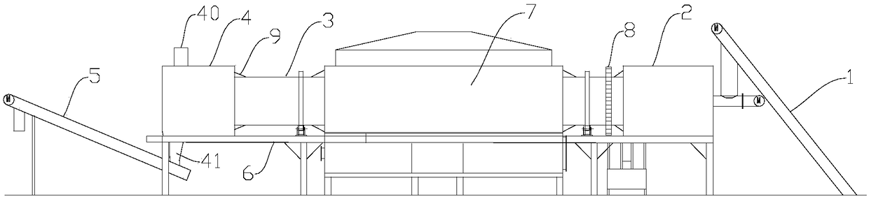
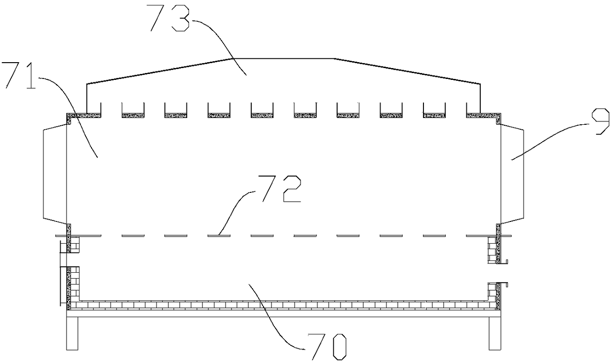
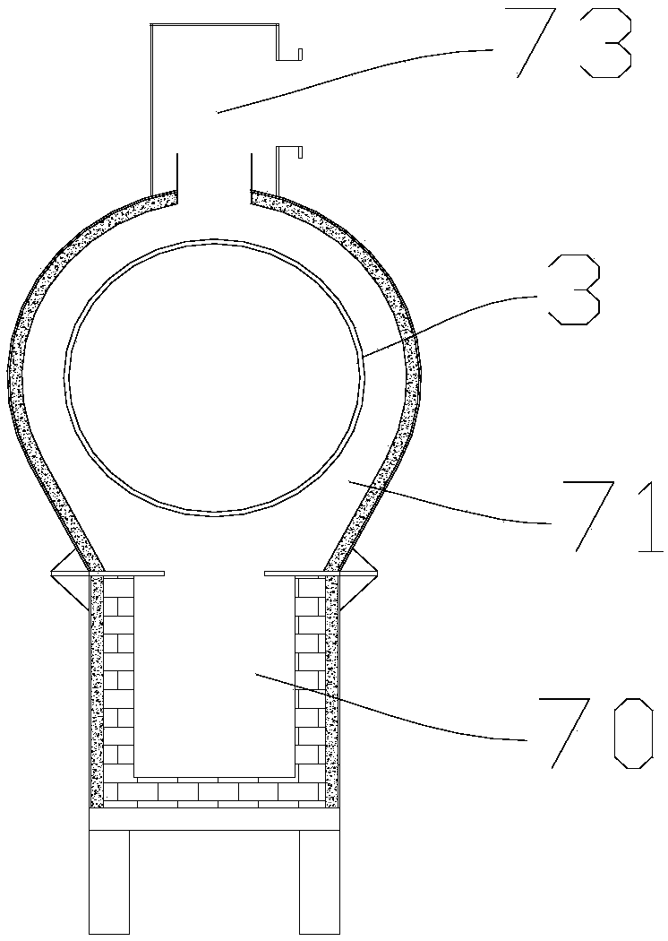
[0033] Such as Figures 1 to 5 As shown, the present invention provides a sealed pyrolysis furnace that continuously feeds and discharges materials, which includes a screw feeder 1, a feed bin 2, a pyrolysis furnace barrel 3, a discharge bin 4, and a screw outlet that are sequentially connected along the material conveying direction. Feeder 5, the feed bin 2 and the discharge bin 4 are fixedly arranged on the frame 6, the top of the discharge bin 4 is provided with a pyrolysis gas outlet, and the bottom is provided with a pyrolysis carbon outlet, and the pyrolysis The furnace drum 3 is supported above the frame 6 by a number of supporting rollers, and the outer wall of the pyrolysis furnace d...


PUM

PropertyMeasurementUnit
lengthaaaaaaaaaa
widthaaaaaaaaaa
thicknessaaaaaaaaaa

Abstract

The invention relates to a sealing pyrolyzing furnace achieving continuous feeding and discharging. The furnace comprises a screw feeder, a feeding bin, a pyrolyzing furnace cylinder, a discharging bin and a screw discharge bin which are sequentially connected in the material conveying direction, the feeding bin and the discharge bin are fixedly arranged on a rack, the pyrolyzing furnace cylinderis supported on the upper portion of the rack through multiple rollers, the outer wall of the pyrolyzing furnace cylinder is sleeved with a gear ring, the rack is provided with a driving mechanism driving the pyrolyzing furnace cylinder to rotate along the central axis through the gear ring, one end of the pyrolyzing furnace is communicated with the feeding bin, the other end of the pyrolyzing furnace is communicated with the discharge bin, a heating pyrolyzing mechanism is arranged in the middle of the pyrolyzing furnace and comprises a combustion chamber located on the lower portion and a pyrolyzing chamber located on the upper portion, openings allowing the pyrolyzing furnace to penetrate through are formed in the left side and the right side of the pyrolyzing chamber, and elastic sealing structures preventing air leakage are arranged on the joints of the pyrolyzing furnace cylinder and the feeding bin, the discharge bin and the pyrolyzing chamber. The sealing pyrolyzing furnace hasthe advantages that the structure is reasonable, continuous feeding and discharging can be achieved, the sealing effect is good, the safety is good, and the pyrolyzing efficiency is high.

Description

technical field [0001] The invention belongs to the field of pyrolysis recycling of wastes rich in organic matter, and in particular relates to a sealed pyrolysis furnace for continuously feeding and discharging materials. Background technique [0002] Wastes rich in organic matter mainly include organic sludge and waste plastics (including circuit boards, plastic packaging materials, etc.). On the one hand, these organic wastes accumulate space and pollute the environment, requiring urgent treatment. On the other hand, they contain a large amount of organic matter. After pyrolysis, pyrolytic charcoal, gas, and fuel oil with high added value can be obtained. [0003] Existing organic waste pyrolysis furnaces and corresponding pyrolysis methods usually have the following deficiencies: 1) The material cannot be continuously fed in and out. Usually, after the feeding of a furnace is completed, it is sealed and then pyrolyzed. After the material is discharged, it is repeated. S...

Claims


Application Information

Patent Timeline
Patent Type & Authority Applications(China)
IPC IPC(8): C10B53/07C10B53/00
CPCY02P20/143C10B53/07C10B53/00
Inventor 方阳春陈威詹仲武李凛凛
Owner 湖北春阳环保装备有限公司
Why Eureka
Try Eureka