Energy-saving control method for ball-milling machine
An energy-saving control, ball mill technology, applied in the industrial field to achieve the effect of preventing delay
- Summary
- Abstract
- Description
- Claims
- Application Information
AI Technical Summary
Problems solved by technology
Method used
Image
Examples
Embodiment 1
[0080] An energy-saving control method for a ball mill, comprising the following steps:
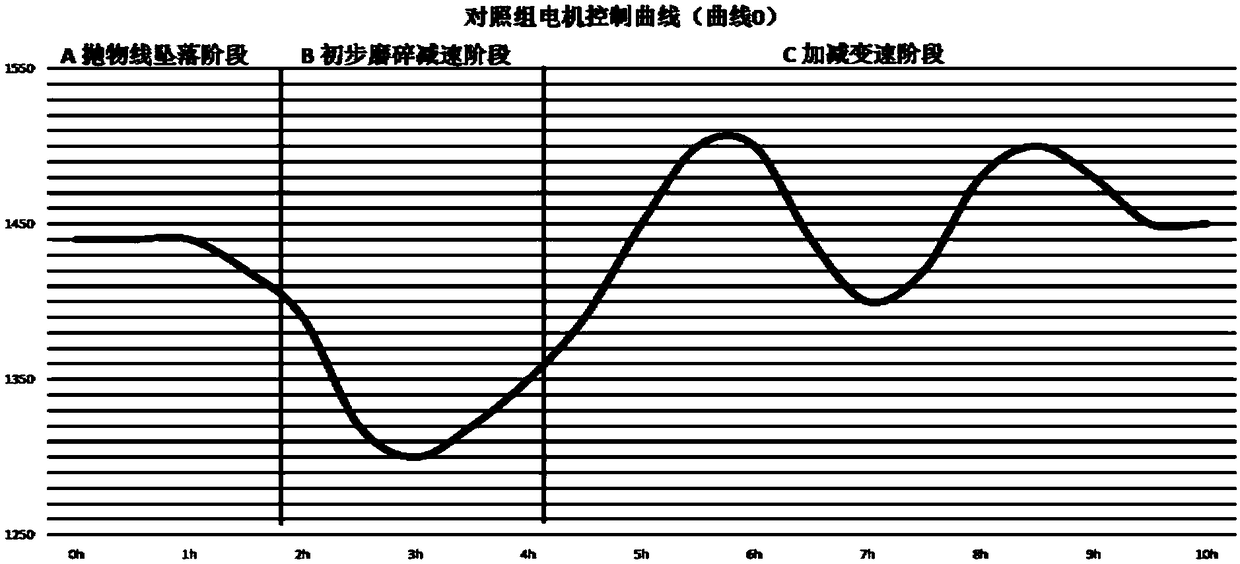
[0081] Set the control group: set the control variables, and then use the system to monitor the different working stages of the ball mill in use, and obtain the first set of control control curve Q0;
[0082] Correction control program: According to the content of the first group of control control curves, in the first correction, a certain speed is increased or decreased in different working stages to form a control curve Q1; the corresponding values of Q1 and Q0 in the different working stages The energy consumption is compared, and the better control curve corresponding to the smaller energy consumption is selected as the second set of control control curves;
[0083] Obtain the optimal curve: repeat the above correction n times (n≥1, n∈N*), and compare the control control curve of the nth group with the control curve Qn at the nth correction to obtain the optimal curve under the condi...
Embodiment 2
[0088] This embodiment is an embodiment combined with a specific implementation manner on the basis of the above-mentioned embodiment 1. The parameters listed in this embodiment are only one of the specific implementation manners, and are not intended to be limitations of relevant operational implementation technical solutions.
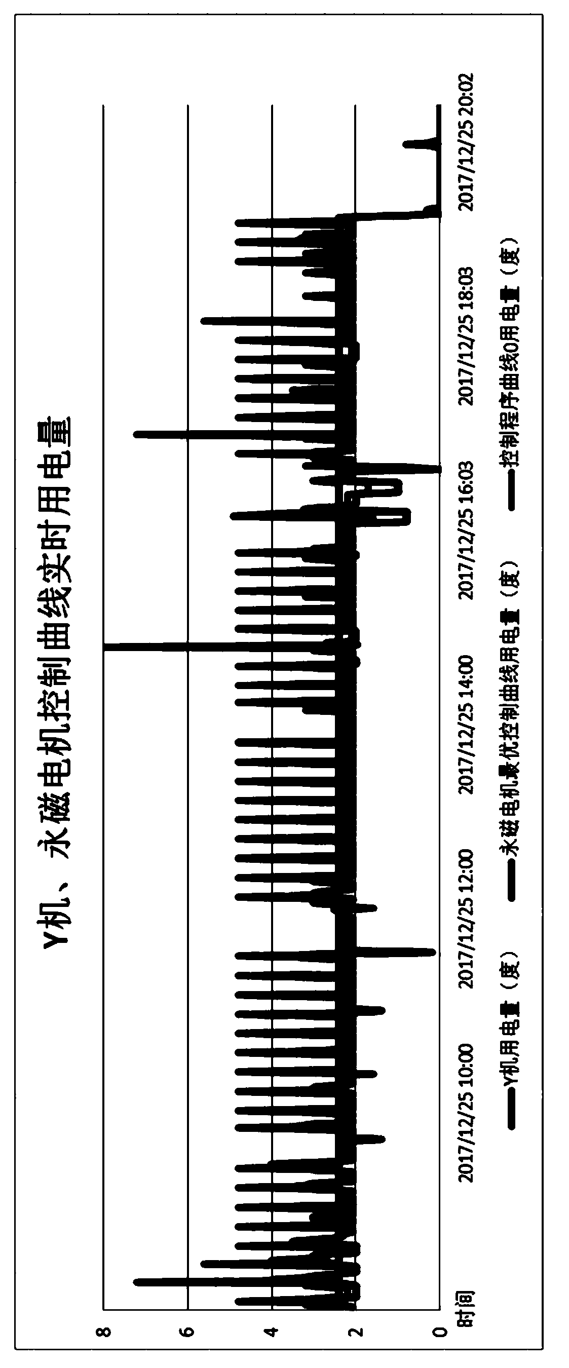
[0089] A ball mill with a widely used charge is selected as the test object, and the lining materials are rubber, medium aluminum and high aluminum. The input material formula and the ball lining material are fixed as external factors, the ratio of raw materials, water and grinding body is fixed at 1:0.45:1.5 as a control variable, and the filling amount of ball stones is maintained at 50% of the volume of the ball Left and right, several optimal power consumption solution experiments were carried out.
[0090] The control target of the ball mill is to achieve the target particle size of 200 mesh. The motor system uses the same transmission system a...
Embodiment 3
[0100] This embodiment is an embodiment combined with specific implementation manners on the basis of the foregoing embodiments. The difference between this embodiment and the above-mentioned embodiments is that in some embodiments, the working stage is determined by a working stage monitoring system, and the working stage system includes: a vibration sensor, a sound sensor and a pressure sensor; the vibration Sensors, sound sensors and pressure sensors are located inside the ball mill. Because in different working stages, the distribution of materials in the ball mill is not the same, for example, the thickness and proportion of the materials distributed on the inner surface of the ball mill will be different. like image 3 As shown, (a)(b)(c) represent the start-up stage of the ball mill, the preliminary grinding stage and the mature grinding stage, respectively.
[0101] Therefore, in an optional implementation manner, the judgment of the ball mill start-up phase, prelimi...
PUM
 Abstract
Description
Claims
Application Information
 - R&D
- Intellectual Property
- Life Sciences
- Materials
- Tech Scout
- Unparalleled Data Quality
- Higher Quality Content
- 60% Fewer Hallucinations
Browse by: Latest US Patents, China's latest patents, Technical Efficacy Thesaurus, Application Domain, Technology Topic, Popular Technical Reports.
© 2025 PatSnap. All rights reserved.Legal|Privacy policy|Modern Slavery Act Transparency Statement|Sitemap|About US| Contact US: help@patsnap.com


