[0022] The technical solutions in the embodiments of the present invention will be clearly and completely described below with reference to the accompanying drawings in the embodiments of the present invention. Obviously, the described embodiments are only a part of the embodiments of the present invention, but not all of the embodiments. Based on the embodiments of the present invention, all other embodiments obtained by those of ordinary skill in the art without creative efforts shall fall within the protection scope of the present invention.
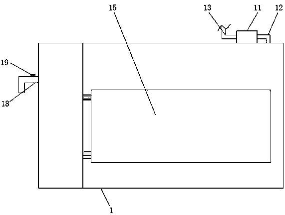
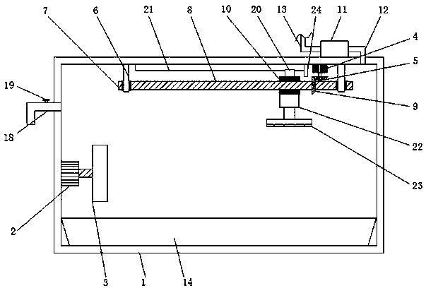
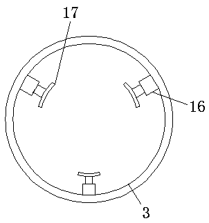
[0023] The embodiment of the present invention provides an iron rod rust removal device for building decoration, such as Figure 1-3 As shown, it includes a vacuum rack 1. A chip storage box 14 is fixedly installed at the bottom of the inner wall of the vacuum rack 1. The chip storage box 14 can be used to collect the scraped iron oxide layer in a closed space to prevent the pollution of waste chips. In the environment, the front of the vacuum frame 1 is movably connected with a door panel 15 through hinges, the left side of the inner wall of the vacuum frame 1 is fixedly installed with the first motor 2, and the first motor 2, the second motor 4 and the bearing sleeve 10 are arranged, so that the iron rods follow When the first motor 2 rotates, the abrasive paper 23 can move left and right along with the bearing sleeve 10 to achieve the effect of removing rust efficiently and quickly. A first electric push rod 16 is fixedly installed on the inner wall of the frame 3 , and an arc-shaped fixing block 17 is fixedly installed on the side of the first electric push rod 16 away from the inner wall of the clamping frame 3 . The telescopic effect of the rod 16 can effectively clamp iron rods of different sizes, so that the iron rod rust removal device for building decoration has a wider application range. The top of the inner wall of the vacuum frame 1 is fixedly installed with a second motor 4. The output end of the motor 4 is fixedly installed with the first bevel gear 5 through the coupling, the top of the inner wall of the vacuum frame 1 is fixedly installed with the connecting frame 6, the left side of the connecting frame 6 is inlaid with a bearing seat 7, and the inside of the bearing seat 7 is fixed A threaded rod 8 is inserted.
[0024] The surface of the threaded rod 8 is fixedly sleeved with a second bevel gear 9, and the second bevel gear 9 and the first bevel gear 5 are meshed with each other. A threaded sleeve 10 is provided inside the vacuum frame 1, and the top of the threaded sleeve 10 is fixedly installed with Slider 20, a slide rail 21 is fixedly installed on the top of the inner wall of the vacuum rack 1, the slide rail 21 is slidably connected with the slider 20, a limit block 24 is fixedly installed on the top of the vacuum rack 1, and the limit block 24 is located on the right side of the slide rail 21 , the threaded sleeve 10 is threadedly connected with the threaded rod 8, the bottom of the threaded sleeve 10 is fixedly installed with a second electric push rod 22, and the side of the second electric push rod 22 away from the threaded sleeve 10 is fixedly installed with a frosted plate, and the surface of the frosted plate is glued The abrasive paper 23 is connected, and the second electric push rod 22 is arranged so that the abrasive paper 23 can fit with iron rods of different sizes. The electric push rod 22, also known as a linear drive, can be considered as an extension of the rotary motor in terms of structure, The electric push rod 22 is a new type of linear actuator mainly composed of a motor push rod and a control device. The top of the vacuum frame 1 is fixedly installed with an air pump 11. One side is connected, the input end of the air pump 11 is connected with an air inlet pipe 13, the left side of the inner wall of the vacuum frame 1 is connected with an air outlet pipe 18, and the top of the air outlet pipe 18 is inlaid with an air outlet valve 19. 18. Fill the vacuum frame 1 with inert gas, and exhaust the original oxygen of the vacuum frame 1 through the gas outlet pipe 18 to form gas convection to prevent secondary oxidation of the iron rod.
[0025] Working principle: When the iron rod needs to be derusted, open the door 15, put the iron rod into the entrance of the clamping frame 3, open the first electric push rod 16 to clamp the iron rod, close the door 15, open the second After the electric push rod 22 presses the abrasive paper 23 against the iron rod, the first motor 2 is turned on to drive the iron rod to rotate, and the second motor 4 is turned on. The meshing effect of the first bevel gear 5 and the second bevel gear 9 makes the threaded rod rotate. 8. Rotate and drive the threaded sleeve 10 to move in the horizontal direction to remove the oxide layer on the surface of the iron rod. At the same time, turn on the air pump 11 to pass the inert gas into the vacuum frame 1. At the same time, open the air outlet valve 19 to form a convection of gas inside the vacuum frame 1. , the oxygen in the vacuum frame 1 is discharged to prevent the secondary oxidation of the iron rod.
[0026] To sum up, the iron rod rust removal device for building decoration has a simple structure and is convenient to use. The motor 2, the second motor 4 and the bearing sleeve 10 make the iron rod rotate with the first motor 2, and the abrasive paper 23 can move left and right with the bearing sleeve 10 to achieve the effect of efficient and rapid removal of rust, and a chip storage box is provided. 14. The scraped iron oxide scrap layer can be collected in a closed space to prevent the scrap from polluting the environment.
[0027] In addition, by setting the air pump 11, the air inlet pipe 13 and the air outlet pipe 18, the vacuum frame 1 is filled with inert gas, and the original oxygen of the vacuum frame 1 is removed through the air outlet pipe 18 to form gas convection to prevent secondary oxidation of the iron rod, The provision of the clamping frame 3 can effectively clamp iron rods of different sizes through the telescopic effect of the first electric push rod 16 , so that the iron rod rust removal device for building decoration has a wider application range.
[0028] It should be noted that, in this document, relational terms such as first and second are used only to distinguish one entity or operation from another entity or operation, and do not necessarily require or imply any relationship between these entities or operations. any such actual relationship or sequence exists. Moreover, the terms "comprising", "comprising" or any other variation thereof are intended to encompass non-exclusive inclusion such that a process, method, article or device comprising a list of elements includes not only those elements, but also includes not explicitly listed or other elements inherent to such a process, method, article or apparatus.
[0029] Although embodiments of the present invention have been shown and described, it will be understood by those skilled in the art that various changes, modifications, and substitutions can be made in these embodiments without departing from the principle and spirit of the invention and modifications, the scope of the present invention is defined by the appended claims and their equivalents.