
High-pressure abrasive water-jet rock coring drilling machine

An abrasive water jet and coring drill technology is used in fractured rock, sandstone coring and small-diameter non-destructive coring drilling machines, and conglomerate fields. , affecting the accurate evaluation of shale oil and gas reservoirs, etc., to achieve the effects of low noise, convenient operation, compact and reasonable structure

Inactive Publication Date: 2018-08-28
SINOPEC SHENGLI OILFIELD +1
View PDF5 Cites 5 Cited by
  • Summary
  • Abstract
  • Description
  • Claims
  • Application Information

AI Technical Summary

Problems solved by technology

For example, when using micro-CT scanning to study the microscopic pore structure inside the rock, the diameter of the rock test sample is often between 3mm-6mm, and it is required that the internal structure of the rock should not be microscopically affected during the 3mm-6mm coring process. Nanoscale damage, otherwise it will seriously affect the research results of the microscopic pore structure characteristics inside the rock
For some fractured rocks with high strength (such as shale), due to the existence of internal fractures in the shale itself and the fact that shale is a brittle material with high strength, it is easy to cause the original The expansion of fractures and the generation of new fractures affect the accurate evaluation of shale oil and gas reservoirs
Therefore, the common mechanical coring method severely restricts the microscale research of rocks in unconventional oil and gas reservoirs.

Method used


Image

  • High-pressure abrasive water-jet rock coring drilling machine
  • High-pressure abrasive water-jet rock coring drilling machine
  • High-pressure abrasive water-jet rock coring drilling machine

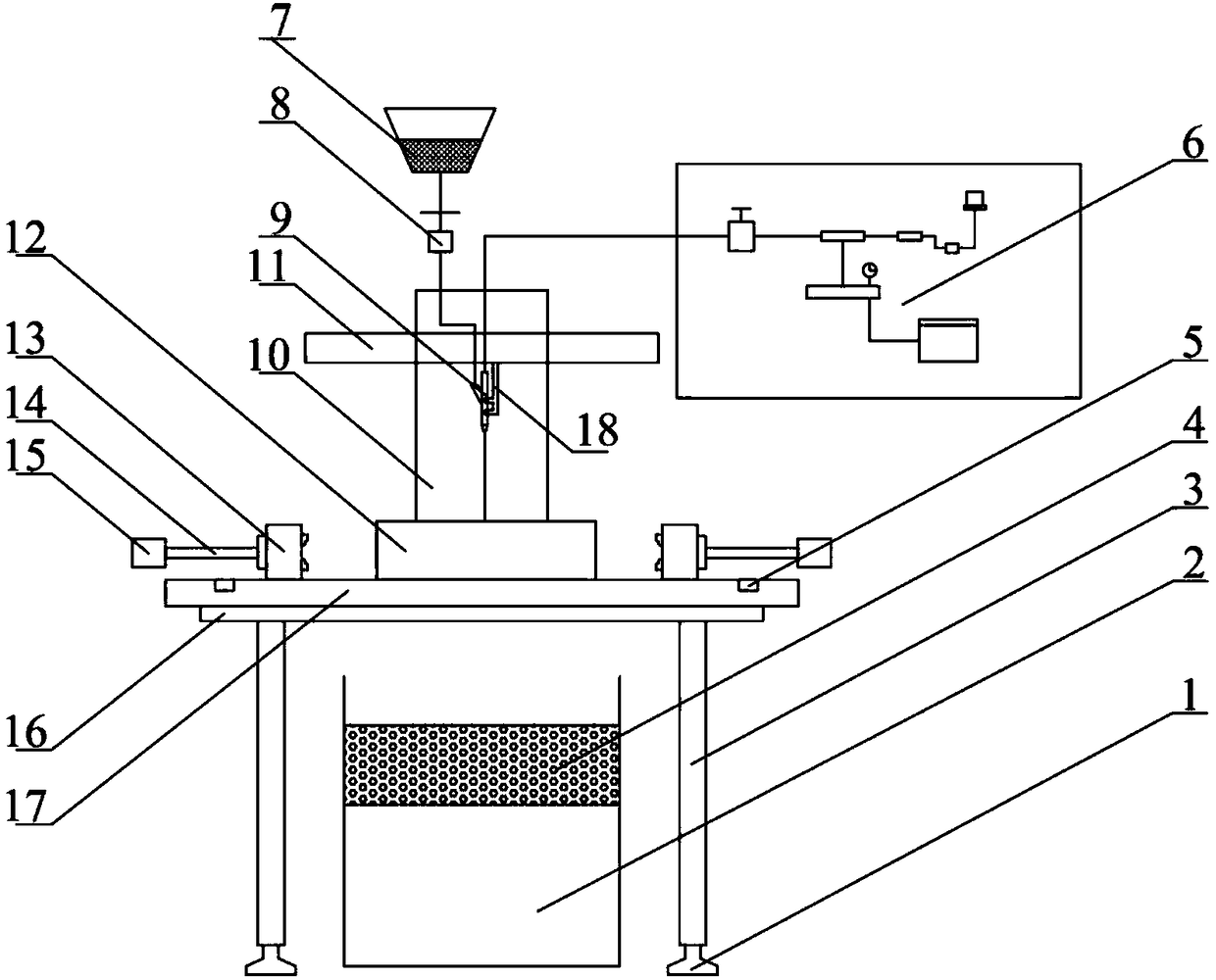
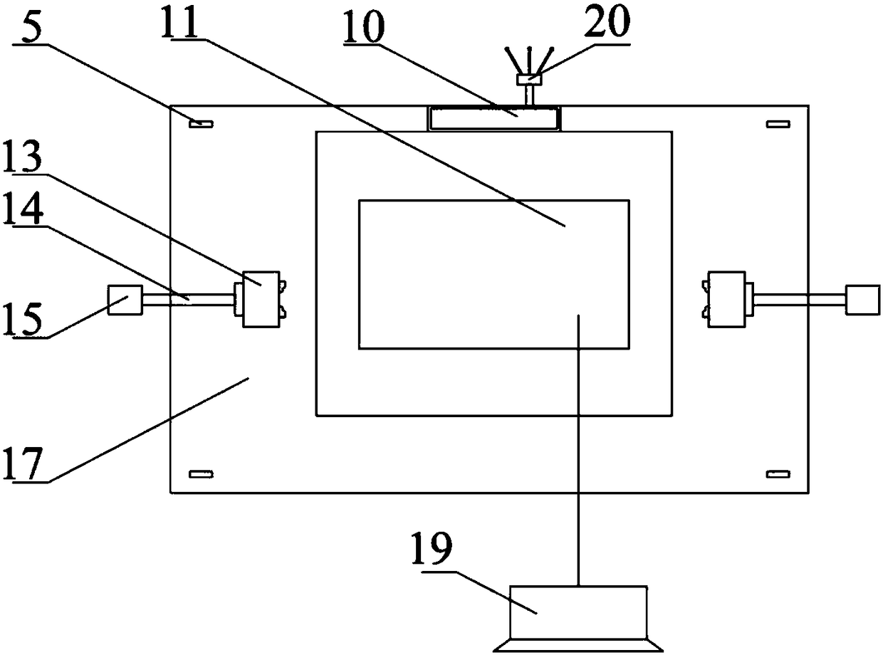
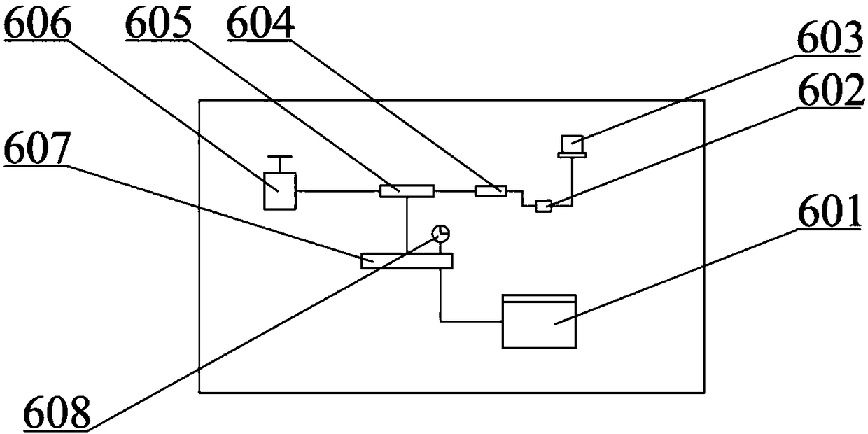
Examples


Embodiment Construction

[0025] The present invention will be further described below in conjunction with the accompanying drawings and embodiments.

[0026] Such as Figure 1-3 As shown, a high-pressure abrasive water jet rock coring drilling machine provided by the present invention includes a drilling machine table 17, and a support frame 10 is arranged in the middle above the drilling machine table 17, and the support frame 10 is used to support the mechanical arm control system 11 , the mechanical arm control system 11 is provided with an up and down transmission rack, and the transmission shaft end of the rotating handle 20 is provided with a transmission gear, and the transmission gear and the transmission rack are engaged and driven by rotating the rotating handle 20 to drive The manipulator control system 11 moves up and down. The manipulator control system 11 is connected to the computer 19. The manipulator 18 is connected to the bottom of the manipulator control system 11. The end of the ma...


PUM


Abstract

The invention discloses a high-pressure abrasive water-jet rock coring drilling machine which comprises a drilling machine table-board, wherein a support frame is arranged at a middle position above the drilling machine table-board; the support frame is used for supporting a manipulator control system; a transmission rack in a vertical direction is arranged on the manipulator control system; a transmission gear is arranged at a transmission shaft end of a rotating handle; the transmission gear and the transmission rack are meshed by rotating the rotating handle to further drive the manipulatorcontrol system to move up and down; the manipulator control system is connected with a computer; a manipulator is connected below the manipulator control system; a downward nozzle is fixed at the endof the manipulator; the nozzle is respectively connected with a high-pressure water supply device and an abrasive tank by virtue of pipelines; a group of three-jaw chucks is symmetrically arranged atpositions on two sides of the support frame above the drilling machine table-board. The high-pressure abrasive water-jet rock coring drilling machine disclosed by the invention is safe and reasonablein overall structural design, is applicable to coring of rock of various lithology and any size, and is particularly applicable to nondestructive coring of high-strength fissured rock, conglomerate rock and sandstone and small-diameter rock.

Description

technical field [0001] The invention relates to the field of rock coring equipment, in particular to a high-pressure abrasive water jet for coring cracked rocks, conglomerate and sandstone with high strength and a small-diameter non-destructive core drilling machine. Background technique [0002] Rock coring is necessary for the research of rock mechanics, seepage and pore structure in mineral investigation, oilfield survey, geological research and geotechnical engineering testing. The degree of damage to the interior of the rock during coring directly affects the accuracy of the test of basic rock parameters such as rock mechanics, seepage, and porosity. [0003] Rock is a hard and brittle material with the characteristics of high hardness, high brittleness and low fracture toughness, and it is easy to generate damage inside it during the coring process. Ordinary mechanical coring methods are likely to cause secondary damage to the rock during the coring process, resulting...

Claims


Application Information

Patent Timeline
Patent Type & Authority Applications(China)
IPC IPC(8): B24C1/04B24C7/00B24C9/00G01N1/04
CPCB24C1/045B24C7/0007B24C9/00B24C9/006G01N1/04
Inventor 宋明水侯江鹏向奎李静张学才王建东汪勇曹海防贺伦俊吕建波
Owner SINOPEC SHENGLI OILFIELD
Learn More