Solar lawn lamp construction machine for garden lawn beautifying and ornament

A technology of solar energy and lawn lamps, applied in infrastructure engineering, chemical instruments and methods, batching and batching instruments, etc., can solve problems such as high labor intensity, long time consumption, and cumbersome and complicated processes, so as to reduce labor intensity and improve work efficiency. Efficiency, simple operation effect

Inactive Publication Date: 2018-08-28
李猛
View PDF0 Cites 0 Cited by
  • Summary
  • Abstract
  • Description
  • Claims
  • Application Information

AI Technical Summary

Problems solved by technology

[0003] In order to solve the above problems, the present invention provides a solar lawn lamp construction machine for garden lawn beautification and embellishment, which can solve the need to manually lay the foundation in the process of installing solar lawn lamps. The process is cumbersome and complicated. When laying the foundation, people usually use tools The ingredients are transported to the existing mixer for mixing, but the mixing is not uniform, and personnel are required to add ingredients into the mixer until the proportion is correct. After mixing, people directly inject the cement slurry into the pit without compacting the surrounding of the pit. Long time-consuming, labor-intensive and low-efficiency problems, can realize automatic compaction, automatic batching, multi-directional mixing and uniform grouting functions of solar lawn lights, automatic control of batching ratio, multi-directional mixing, uniform mixing, uniform grouting, automatic on-site The pit surface is compacted, no human operation is required, the time is short, and it has the advantages of simple operation, low labor intensity and high work efficiency.

Method used


Image

  • Solar lawn lamp construction machine for garden lawn beautifying and ornament
  • Solar lawn lamp construction machine for garden lawn beautifying and ornament
  • Solar lawn lamp construction machine for garden lawn beautifying and ornament

Examples


Embodiment Construction

[0028] In order to make the technical means, creative features, goals and effects achieved by the present invention easy to understand, the present invention will be further described below in conjunction with specific illustrations. It should be noted that, in the case of no conflict, the embodiments in the present application and the features in the embodiments can be combined with each other.

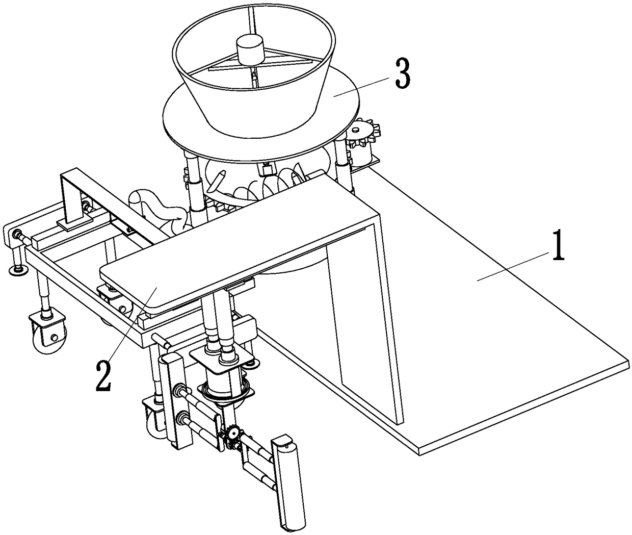
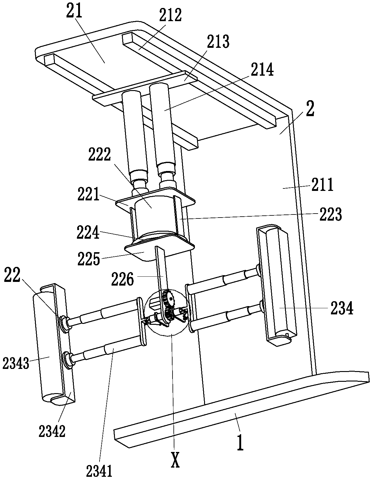
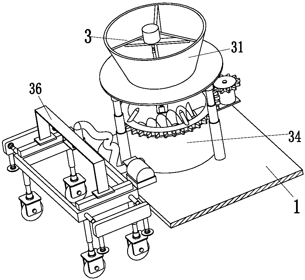
[0029] Such as Figure 1 to Figure 8 As shown, in order to achieve the above object, the present invention adopts the following technical solutions: a solar lawn lamp construction machine for garden lawn beautification and embellishment, including a mobile platform 1, a rolling device 2 and a grouting device 3, and the rolling device 2 is on the edge of the pit. Compacting with the ground, the grouting device 3 grouts the pit, the rolling device 2 is installed on the right side of the front end of the mobile platform 1, the left end of the mobile platform 1 is provided with a semicir...


PUM


Abstract

The invention relates to a solar lawn lamp construction machine for garden lawn beautifying and ornament. The solar lawn lamp construction machine for garden lawn beautifying and ornament comprises amoving platform, a roll-pressing device and a grouting device; the roll-pressing device is arranged on the right side of the front end of the moving platform; a semi-circular groove is formed in the left end of the moving platform; the grouting device is arranged on the left side of the front end of the moving platform; the roll-pressing device and the grouting device are cooperatively used to complete automatic compaction, automatic proportioning, multi-azimuth stirring and uniform grouting processes of the solar lawn lamp. The solar lawn lamp construction machine for garden lawn beautifyingand ornament can solve the problems that the foundation needs to be laid manually in the conventional solar lawn lamp mounting process, the process is tedious and complex, people conveys the materialsinto the conventional stirring machine usually by virtue of tools to stir, the stirring is non-uniform, people need to add the materials into the stirring machine at the later stage until the proportion is correct, people directly injects cement slurry into a pit after stirring, the periphery of the pit is not compacted, and the process is high in time consumption, high in labor intensity and lowin efficiency.

Description

technical field [0001] The invention relates to the technical field of garden lawn construction, in particular to a solar lawn lamp construction machine for beautifying and embellishing garden lawns. Background technique [0002] Solar lawn lights are composed of photovoltaic panels of solar cell components, ultra-bright LED light sources, maintenance-free rechargeable batteries, automatic control circuits, lamps, etc., and mainly use the energy of solar cells to work. When the sun shines on the solar cells during the day , convert light energy into electrical energy and store it in the battery, and then the battery provides power for the LED light-emitting diode of the lawn lamp at night. Its advantages are mainly safety, energy saving, convenience, and environmental protection. It is suitable for garden lawn beautification embellishment, At the same time, it is also suitable for sites with high mobility requirements, difficult circuit laying, and high waterproof requiremen...

Claims


Application Information

Patent Timeline
Patent Type & Authority Applications(China)
IPC IPC(8): B28C5/16B28C5/08B28C7/06B28C7/04E02D15/04
CPCB28C5/16B28C5/0806B28C7/0418B28C7/06E02D15/04
Inventor 李猛
Owner 李猛
Why Eureka
Try Eureka