Deposition chamber and film deposition device

A deposition cavity and cavity technology, which is applied in the field of magnetron sputtering, can solve the problems of instability and unevenness of the deposition process, and achieve the effects of overcoming the instability of the deposition process, improving the stability and overcoming the unevenness.

Active Publication Date: 2018-08-28
BEIJING NAURA MICROELECTRONICS EQUIP CO LTD
View PDF8 Cites 5 Cited by
  • Summary
  • Abstract
  • Description
  • Claims
  • Application Information

AI Technical Summary

Problems solved by technology

The deposition chamber can not only shield the plasma in the lining during the deposition process, thereby preventing the plasma particles from falling into the bottom of the chamber, but also, compared with the prior art, the setting of the shield makes the deposition chamber unnecessary Then set the pressure ring, which not only avoids the particle pollution caused by the detachment of the deposition film when the pressure ring and the tray are separated from each other after the process, but also overcomes the instability of the deposition process caused by the setting of the pressure ring during the process. At the same time, it also overcomes the unevenness of the deposited film caused by the setting of the pressure ring, ensuring the stability of the entire process and the uniformity of the film deposition

Method used


Image

  • Deposition chamber and film deposition device
  • Deposition chamber and film deposition device
  • Deposition chamber and film deposition device

Examples


Embodiment 1

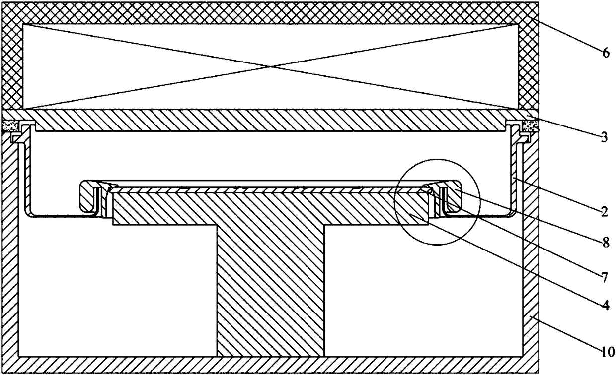
[0036] This embodiment provides a deposition chamber, such as Figure 4 and Figure 5 As shown, it includes a cavity 1, a liner 2 surrounding the side wall of the cavity 1, a target 3 and a base 4, the target 3 is set above the top opening of the liner 2, and the base 4 is set on the liner 2 The lower part of the bottom opening also includes a shielding member 5 , which is fixedly arranged around the periphery of the base 4 , and the orthographic projection of the shielding member 5 on the target 3 covers the bottom of the inner liner 2 .

[0037] Wherein, the process of depositing thin films on the substrate in the deposition chamber is carried out in the lining 2 . Before the process starts, the susceptor 4 moves towards the target 3 so as to abut against the bottom of the inner liner 2, thereby forming a relatively closed plasma process area. The orthographic projection of the shield 5 on the target 3 covers the bottom of the inner liner 2. During the deposition process, ...

Embodiment 2

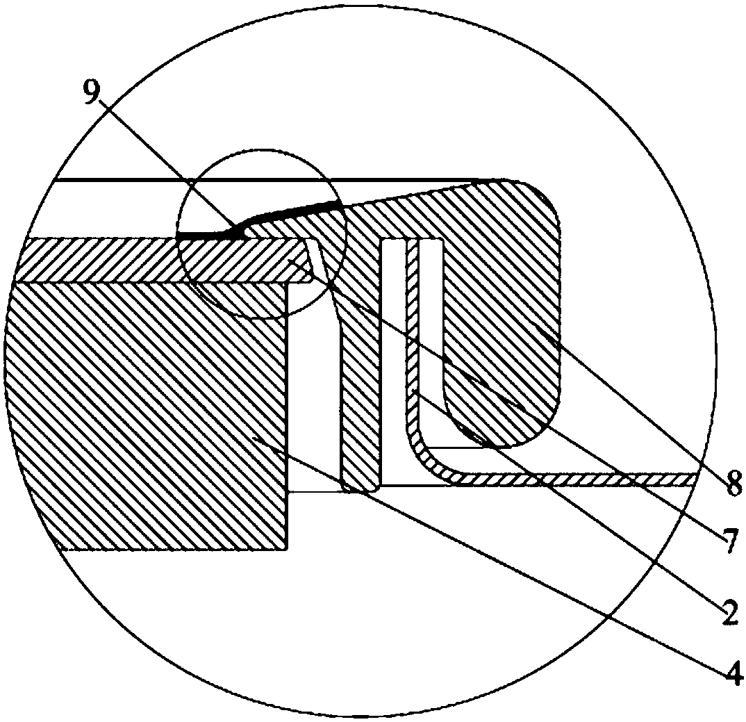
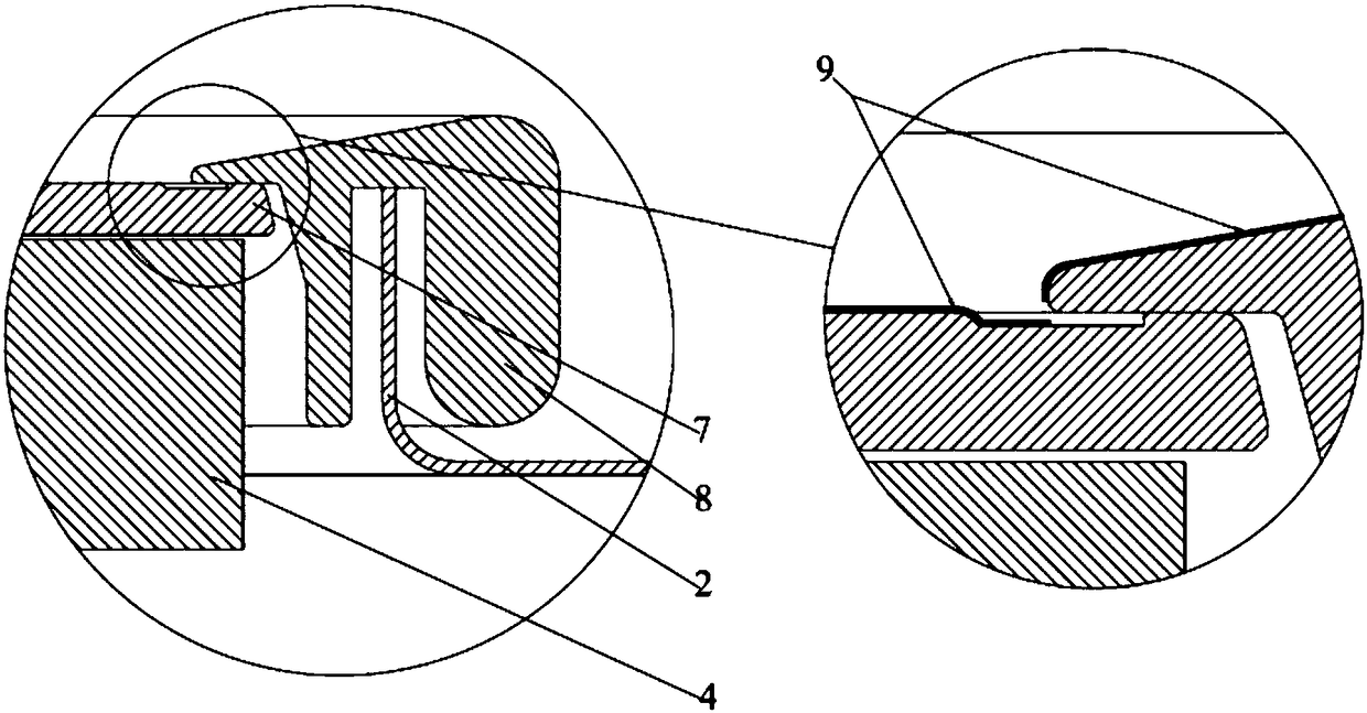
[0048] This embodiment provides a deposition chamber, which is different from Embodiment 1, as Figure 6 As shown, the shutter 5 includes an annular plane 51, a first cylindrical structure 52 and a second cylindrical structure 53, wherein one end of the first cylindrical structure 52 is connected to the outer periphery of the annular plane 51; The first end is connected to the inner periphery of the annular plane 51 , and the second end is fixed to the bottom surface of the carrier 41 .

[0049] Wherein, the height of the second cylindrical structure 53 is smaller than the height of the first cylindrical structure 52 .

[0050] In this embodiment, the shielding member 5 is a rectangular groove; the rectangular groove is recessed away from the inner liner 2 . The side wall on one side of the rectangular groove is fixedly arranged on the bottom surface of the carrier 41, the other side wall of the rectangular groove is at least partly interlaced with the side wall of the inner ...

Embodiment 3

[0055] This embodiment provides a film deposition device, including the deposition chamber in any one of Embodiments 1-2.

[0056] By adopting the deposition chamber in any one of the embodiments 1-2, not only the film deposition quality of the film deposition device is improved, but also the stability of the film deposition process of the film deposition device is improved.


PUM


Abstract

The invention provides a deposition chamber and a film deposition apparatus. The deposition chamber comprises a cavity, a liner encircling the sidewall of the cavity, a target and a substrate, whereinthe target is arranged above the top opening of the liner, and the substrate is arranged below the bottom opening of the liner. The deposition chamber further comprises a shielding member which is fixedly arranged around the periphery of the substrate, wherein the orthographic projection of the shielding member on the target covers the bottom of the substrate. The deposition chamber can prevent plasma particles from falling into the bottom of the cavity and does not need extra pressure ring, thereby avoiding particle contamination caused by falling-off of a deposited film when the pressure ring and a tray are separated from each other after completion of process; and the deposition chamber overcomes the defect of instability of a deposition process due to the setting of the pressure ringand the defect of nonuniformity of the deposited film caused by the setting of the pressure ring, thereby ensuring the stability of the entire process and the uniformity of film deposition.

Description

technical field [0001] The invention relates to the technical field of magnetron sputtering, in particular to a deposition chamber and a film deposition device. Background technique [0002] ITO (Indium Tin Oxide) PVD (Physical Vapor Deposition) machine is a device for ITO film deposition in LED production line. The main structure of the ITO machine process chamber used to prepare LED chips is as follows: figure 1 As shown, the cavity 6 at the top of the chamber 10 is provided with a cooling liquid, mainly for cooling the target, and the cavity 6 at the top of the chamber 10 is also provided with a magnetron for controlling the plasma. The main material of the target is ITO, and after the plasma bombards the target, the ITO is deposited on the chip to form a thin film. The inner lining 2 is arranged in the chamber 10, and its function is to protect the inner wall of the chamber 10 to prevent the deposited film from polluting the inner wall of the chamber 10; the base 4 is ...

Claims


Application Information

Patent Timeline
Patent Type & Authority Applications(China)
IPC IPC(8): C23C14/35C23C14/08
CPCC23C14/086C23C14/35
Inventor 武学伟
Owner BEIJING NAURA MICROELECTRONICS EQUIP CO LTD
Why Eureka
Try Eureka