
Optical resonator

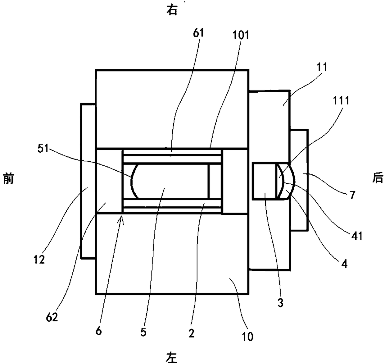
A technology of optical resonant cavity and concave cavity, which is applied in the field of optics, can solve problems affecting the stability of optical parametric oscillation cavity length, phase jitter, etc., and achieve the effect of improving phase stability and reducing phase jitter

Active Publication Date: 2018-08-28
SHANXI UNIV
View PDF7 Cites 4 Cited by
  • Summary
  • Abstract
  • Description
  • Claims
  • Application Information

AI Technical Summary

Problems solved by technology

However, in the prior art, the copper crystal furnace is set separately from the piezoelectric ceramics and the output mirror, which will mainly affect the stability of the optical parameter oscillation cavity length and cause phase jitter.

Method used


Image

  • Optical resonator
  • Optical resonator
  • Optical resonator

Examples


Embodiment 1

[0045] Such as Figure 11 As shown, this embodiment utilizes a structurally stable optical cavity to generate frequency-doubled light. Its inventive idea is to convert the difficult-to-adjust optical resonant cavity structure into a stable integral resonant cavity structure, which improves the mechanical stability, and the adjustment process is simple, fast, efficient, and high in precision. Stay at the resonance point for a few minutes without moving in the free running state.

[0046] Specifically, the base frequency light output by the 1550nm single-frequency laser 90 is injected into the optical resonant cavity through the dichroic mirror 91, and the base frequency light passes through the nonlinear crystal 5 in the optical resonant cavity for frequency doubling, and the 775nm frequency doubled light is output through the dichroic mirror 91 , for pumping the optical parametric cavity OPA. The optical resonant cavity is composed of a meniscus concave input mirror 4 and a ...

Embodiment 2

[0048] Such as Figure 12 As shown, this embodiment presents the working principle of using a structurally stable optical resonant cavity to generate compressed light. The pump light is injected into the optical resonant cavity through the dichroic mirror 91, and the pump light passes through the nonlinear crystal 5 in the optical resonant cavity to perform a parametric down-conversion process to obtain the compression of the quantum noise of a certain orthogonal component below the classical shot noise limit. Due to its characteristic of breaking through the limitation of quantum noise, the state light field is used to improve the sensitivity of precision optical measurement and weak gravitational wave signal detection. The cavity structure is the same as in Example 1.


PUM


Abstract

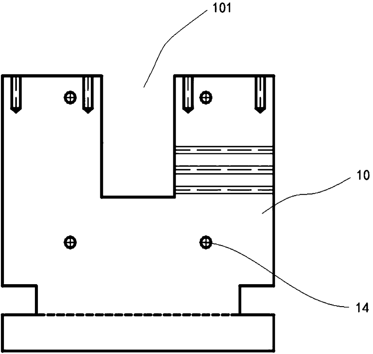
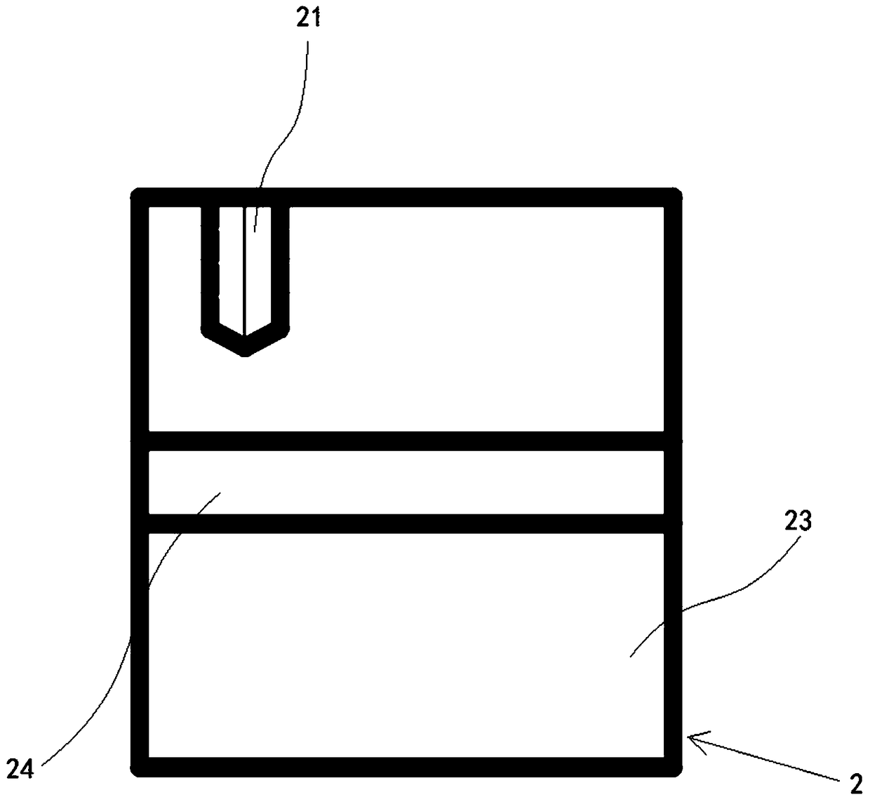
The present invention provides an optical resonator. The optical resonator comprises a housing consisting of a main body portion and a rear end cover, wherein the main body portion has a cavity, and the rear end cover is arranged on the main body portion in a mode for sealing an opening at the rear side of the cavity; a red copper crystal oven with nonlinear crystal arranged in the cavity; and piezoelectric ceramics and an output mirror arranged in the rear end cover, wherein the nonlinear crystal, the piezoelectric ceramics and an optical path of the output mirror communicate in order and arearranged in the same straight line. The objective of the invention is to provide an optical resonator capable of reducing phase jittering and improving the phase stability.

Description

technical field [0001] The invention belongs to the field of optical technology and relates to an optical resonant cavity. Background technique [0002] The squeezed light field is a non-classical light field that compresses the noise of a certain orthogonal component below the shot noise limit. Because it has the characteristics of breaking through the limit of quantum noise, it is used to improve precision optical measurements and weak gravitational wave signals. Sensitivity of detection; in addition, two beams of single-mode squeezed light or one beam of double-mode squeezed light can be used to generate entangled light fields, which are then applied to the research of quantum computing, quantum information and quantum communication. Therefore, the study of a non-classical light source with high compression degree that operates continuously and stably has become a hot spot in current scientific research. As early as 1985, Bell Laboratories in the United States first obse...

Claims


Application Information

Patent Timeline
IPC IPC(8): H01S3/108H01S3/131H01S3/08G02F1/355
CPCG02F1/3551G02F1/3553H01S3/08H01S3/108H01S3/1317
Inventor 郑耀辉张文慧彭堃墀
Owner SHANXI UNIV
Learn More