Sine wave power supply double-freedom-degree spiral motor with position self-locking function

A sine wave, degree of freedom technology, applied in the field of sine wave power supply dual-degree-of-freedom helical motor, can solve the problems of limiting the linear force and efficiency of the motor, the inability to use sine wave power supply, and the complex structure of the motor to achieve the effect of improving flexibility

Active Publication Date: 2018-08-28
SOUTHEAST UNIV
View PDF6 Cites 3 Cited by
  • Summary
  • Abstract
  • Description
  • Claims
  • Application Information

AI Technical Summary

Problems solved by technology

[0003] Existing rotary linear motors can be divided into three types. The first type is a structure with a "chessboard" permanent magnet attached to the outer surface of the mover. The rotation and linear motion of the mover are similar to synchronous motors. The advantage of this type of motor is that Sine wave power supply can be used, but the magnetic circuit that generates rotational motion and the magnetic circuit that moves linearly are coupled to each other, and the position of the mover in the axial direction needs to be locked by an external mechanical structure; the second is a switched reluctance type rotary-linear motor, Here, the mover of the motor is distributed with "chessboard" protrusions. The advantage of this type of motor is that the position of the mover in the axial direction can be self-locked, but it cannot be powered by a sine wave, and the torque ripple is very large; The stator armature coil or the magnetic poles of the mover are arranged according to the spiral. The advantage of this motor is that the structure is intuitive and the control method is simple. can do spiral motion
In addition, the above three motors have another common disadvantage, that is, in order to improve the efficiency of the motor, the mover core can only be made of radial laminations, which makes the mover core have a magnetic barrier in the axial direction, and the reluctance is very low. Large, which limits the linear force and efficiency of the motor

Method used


Image

  • Sine wave power supply double-freedom-degree spiral motor with position self-locking function
  • Sine wave power supply double-freedom-degree spiral motor with position self-locking function
  • Sine wave power supply double-freedom-degree spiral motor with position self-locking function

Examples


Embodiment Construction

[0030] The present invention will be further described below in conjunction with the accompanying drawings.

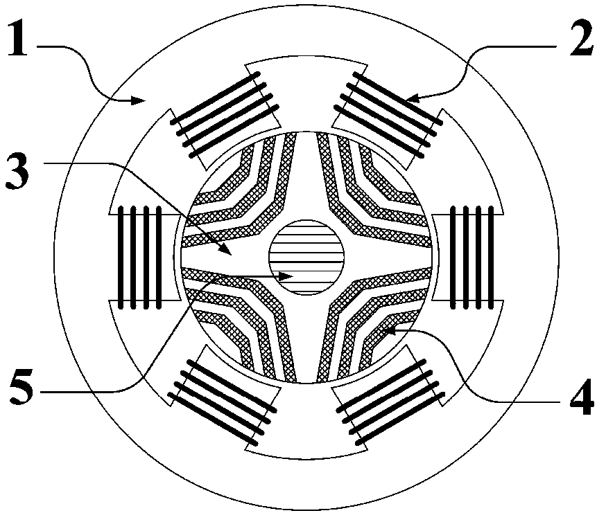
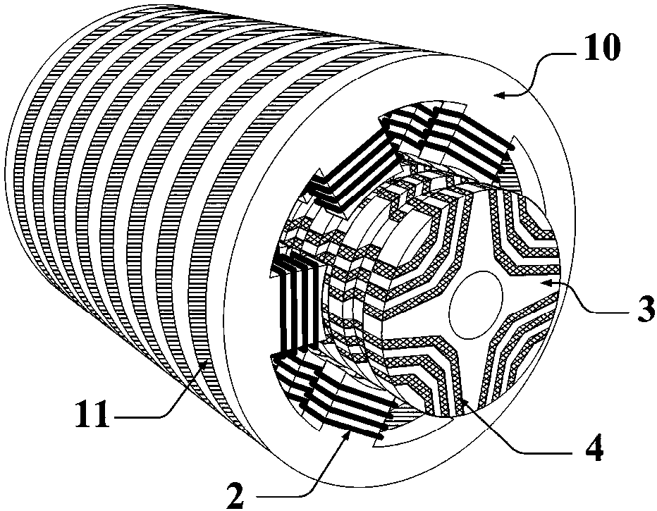
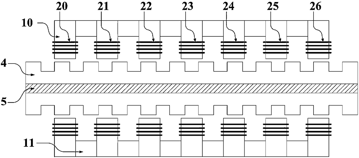
[0031] Such as figure 1 and figure 2 As shown, the sine wave power supply dual-degree-of-freedom spiral motor with position self-locking function of the present invention includes a stator core 1, an armature winding 2, a mover non-magnetic base 3, a mover magnetic core 4, and a rotating shaft 5; Iron core 1 is composed of stator power iron core 10 and stator annular iron core 11, and armature winding 2 is placed on stator power iron core 10; stator power iron core 10 and stator annular iron core 11 are arranged alternately and closely arranged along the axial direction; It is located on the non-magnetic base 3 of the mover; the non-magnetic base 3 of the mover, the magnetic core 4 of the mover and the rotating shaft 5 together constitute the mover.

[0032] Such as image 3 As shown, the mover presents a salient pole structure in the axial direction; the armature ...


PUM


Abstract

The invention discloses a sine wave power supply double-freedom-degree spiral motor with position self-locking function, comprising a rotor iron core, an armature winding, a rotor non-magnetic conduction base, a rotor magnetic iron core and a rotating shaft. A plurality of boss units are arranged on the inner wall of the stator iron core, and each group of boss units comprises bosses uniformly distributed along the axial direction of the inner wall of the stator iron core. An armature winding is arranged on the boss, and each armature winding is connected with a switch, and the movable sub-magnetic core is located on the non-magnetic-conducting base of the rotor. The rotor is located on the non-magnetic conduction base of the rotor, and the rotor is not connected with the magnetic base, and the rotor magnetic core and the rotating shaft jointly form a rotor. The sine wave power supply double-freedom-degree spiral motor with the position self-locking function is provided, and the characteristics of the axial magnetic field synchronous reluctance motor and the switch reluctance motor are ingeniously combined, and the rotor magnetic core is formed by pressing a silicon steel sheet axis, so that both the rotary motion magnetic circuit and the linear motion magnetic circuit in the rotor iron core do not have magnetic barriers, motor output force and efficiency are high.

Description

technical field [0001] The invention relates to a sine wave power supply double-degree-of-freedom screw motor with a position self-locking function, belonging to the field of motors. Background technique [0002] Rotary linear motors are widely used in today's life, especially in the fields of industrial control, machine tools, robots, drilling, thread processing, office automation, positioning systems, flexible manufacturing and assembly systems, and aerospace, and play a pivotal role. Today's rotary linear motors are usually implemented with multiple motors and mechanical conversion mechanisms, but this implementation leads to bulky and heavy motor systems. The manufacturing process of this motor system is cumbersome, the cost is high, and the efficiency is low; the operation process is complicated and the motion accuracy is low. How to design a simple and lightweight new motor with high precision, high efficiency and high performance that can realize two degrees of freed...

Claims


Application Information

Patent Timeline
Patent Type & Authority Applications(China)
IPC IPC(8): H02K41/06
CPCH02K41/06
Inventor 张淦花为程明朱俊明
Owner SOUTHEAST UNIV
Why Eureka
Try Eureka