Ball-end mill for milling curved surface splicing molds

A ball-end milling cutter and splicing mold technology, applied in milling cutters, manufacturing tools, milling machine equipment, etc., can solve the problems of poor surface quality and high processing cost of processed workpieces, increase contact area, improve processing quality, and improve processing The effect of precision

Inactive Publication Date: 2018-09-04
HARBIN UNIV OF SCI & TECH
View PDF6 Cites 3 Cited by
  • Summary
  • Abstract
  • Description
  • Claims
  • Application Information

AI Technical Summary

Problems solved by technology

[0004] In order to solve the problems of poor surface quality and high processing cost of existing blade type ball end milling cutters, the present invention further provides a ball end milling cutter for curved surface splicing mold milling

Method used


Image

  • Ball-end mill for milling curved surface splicing molds
  • Ball-end mill for milling curved surface splicing molds
  • Ball-end mill for milling curved surface splicing molds

Examples


specific Embodiment approach 1

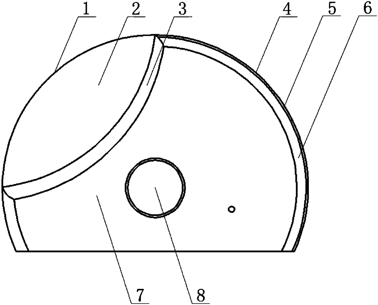
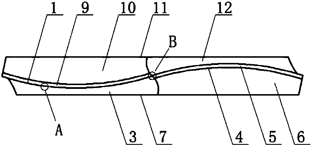
[0023] Specific implementation mode one: as Figure 1~3 As shown, the profile of the ball-end milling cutter for splicing mold milling in this embodiment is in the shape of a round cake, and two cutting edges are processed on the ball-end milling cutter, and the two cutting edges are the first cutting edge 1 and the second cutting edge respectively. Two cutting edges 4, the first cutting edge 1 and the second cutting edge 4 are sinusoidal cutting edges, one side of the first cutting edge 1 is connected with the first rake face 2, and the first rake face 2 is lower than the ball head The upper surface 7 of the milling cutter is set and the two are arranged in parallel, the first rake surface 2 and the upper surface 7 of the ball end milling cutter are transitionally connected through the first groove surface 3, and the other side of the first cutting edge 1 is connected with the first rear Cutter face 9; one side of the second cutting edge 4 is connected with a second rake face...

specific Embodiment approach 2

[0024] Specific implementation mode two: as Figure 1~3 As shown, the first groove surface 3 and the second groove surface 12 in this embodiment are both concave curved surfaces. Such a design increases the contact area between the tool holder and the blade, making it difficult for the blade to loosen during the milling process, thereby improving the machining accuracy of the parts. Other components and connections are the same as those in the first embodiment.

specific Embodiment approach 3

[0025] Specific implementation mode three: as image 3 with Figure 4 As shown, the edge A of the first cutting edge 1 in this embodiment is a composite structure of chamfers 16 and blunt circles 15 . Designed in this way, the structure greatly improves the impact resistance of the cutting edge, reduces the wear rate of the first flank face at the same time, and improves the service life of the tool and the surface processing quality of the workpiece. Other compositions and connections are the same as those in Embodiment 1 or 2.


PUM


Abstract

The invention provides a ball-end mill for milling curved surface splicing molds, relates to a ball-end mill, and solves the problems that by an existing blade type ball-end mill, the surface qualityof a machined workpiece is poor, and the machining cost is high. Two cutting blades are machined on the ball-end mill, one side of the first cutting blade is connected with a first front knife face, the first front knife face is lower than the upper surface of the ball-end mill and is parallel to the upper surface of the ball-end mill, the first front knife face is in transitional connection withthe upper surface of the ball-end mill through a first groove surface, and the other side of the first cutting blade is connected with a first rear knife face; and one side of the second cutting bladeis connected with a second front knife face, the second front knife face is lower than the lower surface of the ball-end mill and is parallel to the lower surface of the ball-end mill, the second front knife face is in transitional connection with the lower surface of the ball-end mill through a second groove surface, the other side of the second cutting blade is connected with a second rear knife face, and a knife point is arranged at a position where the first cutting blade is connected with the second cutting blade. The ball-end mill is used for milling the curved surface splicing molds.

Description

technical field [0001] The invention relates to a ball-end milling cutter, in particular to a ball-end milling cutter for splicing molds with curved surfaces. Background technique [0002] At present, integral ball-end milling cutters or blade-type straight-edge ball-end milling cutters are used for the finishing of automobile panel splicing molds. , resulting in large cutting force and vibration, which in turn affects the machining accuracy, surface quality and tool life; the traditional blade-type ball end milling cutter is easy to loose after the blade is connected with the tool holder; the milling of the curved surface splicing mold will aggravate the impact on the cutting edge of the tool impact, causing excessive wear or damage to the blade before it reaches the blunt standard, which affects the stability and processing quality of the milling system; the tip of the traditional milling cutter cannot participate in cutting, and when the axis of the tool is perpendicular ...

Claims


Application Information

Patent Timeline
Patent Type & Authority Applications(China)
IPC IPC(8): B23C5/02
CPCB23C5/02
Inventor 岳彩旭王彦武马晶
Owner HARBIN UNIV OF SCI & TECH
Why Eureka
Try Eureka