Welding method for bimetal composite pipe

A bimetal composite pipe and welding method technology, applied in welding equipment, metal processing equipment, arc welding equipment, etc., can solve the problems of poor corrosion resistance of weld seams, high welding cost of one-sided welding, and low quality of joints

Inactive Publication Date: 2018-09-07
CHINA UNIV OF PETROLEUM (EAST CHINA)
View PDF6 Cites 6 Cited by
  • Summary
  • Abstract
  • Description
  • Claims
  • Application Information

AI Technical Summary

Problems solved by technology

[0005] Aiming at the many deficiencies in the prior art, the present invention provides a welding method for bimetallic composite pipes, which provides a method for welding bimetallic composite pipes, including mechanical composite pipes and metallurgical composite pipes. The welding surface of the pipe base layer is processed by groove processing, and the groove form is a Y-shaped groove, and then the welding is carried out by TIG or MIG for pre-sealing welding, and the overall welding is completed by superimposing multiple welding passes. The above method It can solve the problems of high welding cost, low quality joints and poor corrosion resistance of weld seams for single-side welding of bimetallic composite pipes

Method used


Image

  • Welding method for bimetal composite pipe
  • Welding method for bimetal composite pipe
  • Welding method for bimetal composite pipe

Examples


Embodiment 1

[0026] A welding method for a bimetal composite pipe, the main steps are as follows:

[0027] Step 1. Processing and treatment of welding groove

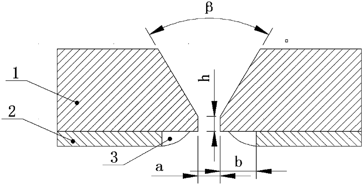
[0028] 101. The welding surface of the bimetallic composite pipe base layer 1 is processed by machining, and the groove is in the form of a Y-shaped groove; the welding surface of the inner lining layer 2 of the bimetallic composite pipe is stripped to a certain extent, and the width is b 5-8mm, using TIG or MIG for pre-sealing welding to form the sealing layer 3, the welding material used is stainless steel or nickel-based welding wire one grade higher than that of the inner lining layer 2, the welding current is 70-90A, argon gas Flow 18L~22L / min;

[0029] 102. Groove cleaning: Use a wire brush to grind and scrub the groove and its vicinity within 25cm to prevent harmful effects of oil and rust on the weld;

[0030] 103. Groove pairing: check the processing quality of the groove, ensure that the groove and its surrounding area a...

Embodiment 2

[0038] A welding method for a bimetallic composite pipe, (in this embodiment, the thickness of the base layer is 12mm, the thickness of the inner lining layer is 2mm, the base layer is L415 pipeline steel, and the inner lining layer is 316L austenitic stainless steel) The main steps are as follows:

[0039] Step 1. Processing and treatment of welding groove

[0040] 101. The welding surface of the bimetallic composite pipe base layer 1 is processed by machining, and the groove is in the form of a Y-shaped groove; the welding surface of the inner lining layer 2 of the bimetallic composite pipe is stripped to a certain extent, and the width is b 5-8mm, using TIG or MIG for pre-sealing welding to form the sealing layer 3, the welding material used is stainless steel or nickel-based welding wire one grade higher than that of the inner lining layer 2, the welding current is 70-80A, argon gas Flow 18L~22L / min;

[0041] 102. Groove cleaning: Use a wire brush to grind and scrub the gro...


PUM

PropertyMeasurementUnit
Thicknessaaaaaaaaaa
Thicknessaaaaaaaaaa
Thicknessaaaaaaaaaa

Abstract

The invention belongs to the field of welding engineering, and particularly relates to a welding method for a bimetal composite pipe. The welding method is used for welding the bimetal composite pipeincluding a mechanical composite pipe and a metallurgical composite pipe. Groove processing treatment is carried out on welding faces of basic layers of the bimetal composite pipe, the groove type isa Y-shaped groove, then, welding is carried out through a manner of adopting TIG or MIG to carry out pre-sealing treatment, the welding of the whole is completed through a manner that multiple weld beads are overlapped, and by means of the method, the problems that according to single side welding of the bimetal composite pipe, the welding cost is high, the joint quality is low, the welding line corrosion resistance is poor and other problems can be solved.

Description

technical field [0001] The invention belongs to the field of welding engineering, and in particular relates to a welding method for a bimetal composite pipe. Background technique [0002] The bimetal composite pipe is formed by combining the base layer and the inner lining layer through a specific processing technology, and is mainly divided into mechanical composite pipe and metallurgical composite pipe. The base layer is carbon steel or low alloy steel, which is responsible for pressure bearing and rigid support of the pipeline, and the inner lining layer is stainless steel or nickel-based alloy, which is responsible for corrosion resistance. It integrates the mechanical properties of the base pipe and the anti-corrosion performance of the corrosion-resistant alloy of the lining pipe, and has been widely used in petroleum and natural gas, chemical industry, electric power, environmental protection, textile and other fields in recent years. [0003] Due to space constraint...

Claims


Application Information

Patent Timeline
IPC IPC(8): B23K9/235B23K9/16B23K9/02
CPCB23K9/02B23K9/16B23K9/235
Inventor 李立英韩彬肖军王勇
Owner CHINA UNIV OF PETROLEUM (EAST CHINA)
Why Eureka
Try Eureka