A method for in-situ sediment restoration

A remediation method and sediment technology, which is applied in chemical instruments and methods, biological sludge treatment, sludge treatment, etc., can solve the problems of low efficiency, lack of in-situ remediation of sediment, and limited injection materials, etc., to improve in-situ The effect of restoration efficiency, simple structure and convenient operation

Active Publication Date: 2021-04-13
SHENZHEN YUANYU ECOLOGICAL SCI & INNOVATION CENT CO LTD
View PDF2 Cites 0 Cited by
  • Summary
  • Abstract
  • Description
  • Claims
  • Application Information

AI Technical Summary

Problems solved by technology

[0006] (1) At present, most of the chemical dosing is artificially added to the water, and the chemical is settled on the surface of the sediment by the gravity of the chemical. When the water flow is large, the chemical may be washed away by the water. Due to the limited contact between the chemical and the sediment, it is greatly The efficiency of the agent is reduced; the existing rake injection process has a large disturbance to the sediment, and there is a situation where the restoration agent overflows. At the same time, the rake injection method is very limited in both the injection depth and the injection material in a single working process , therefore, its existing actual case effects show that the efficiency is low
[0007] (2) Existing research data show that the pollutants are unevenly distributed in the sediment both horizontally and vertically, and there is a lack of targeted equipment in the current in-situ remediation technology;
[0008] (3) Due to the lack of practical dosing equipment, it is impossible to effectively control the degradation environment of sediment pollutants, and the degradation reaction of pollutants in sediment is in an "out of control state", which directly reduces the efficiency of sediment restoration
[0009] To sum up, for the differences in the horizontal and vertical distribution of pollutants in the sediment, the traditional in-situ remediation technology for sediment lacks targeted methods and equipment. In situ repair is less efficient

Method used


Image

  • A method for in-situ sediment restoration
  • A method for in-situ sediment restoration
  • A method for in-situ sediment restoration

Examples


Embodiment 1

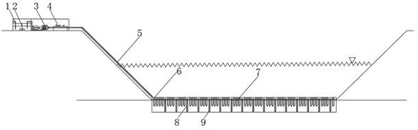
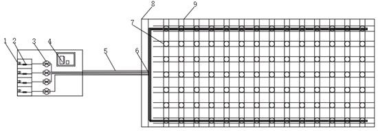
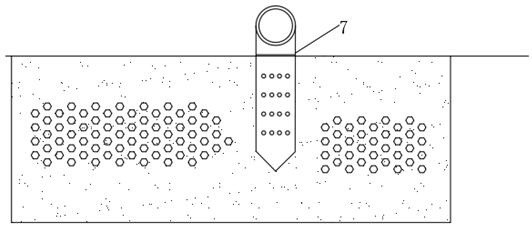
[0036] Such as Figure 1-3 As shown, the present invention is an in-situ sediment restoration equipment, including a heating device 1, a stirring device 2 is fixedly installed on one side of the heating device 1, a pressurization system 3 is arranged on one side of the stirring device 2, and a pressurization system 3 A control system 4 is installed on one side, a pipeline system 5 is fixedly installed under the heating device 1, a venting device 6 is fixedly installed under the pipeline system 5, and an injection device 7 is fixedly installed on one side of the venting device 6. The injection device 7 An anchoring device 8 is fixedly installed below, and a lifting device 9 is fixedly installed on one side of the anchoring device 8 .

[0037] The injection device 7 includes a syringe, a structural part and a protective part. The combined shape of the structural part and the protective part is a cylinder. The front ends of the structural part and the protective part are in the s...


PUM

PropertyMeasurementUnit
diameteraaaaaaaaaa
diameteraaaaaaaaaa
lengthaaaaaaaaaa

Abstract

The invention discloses an in-situ sediment restoration equipment, which comprises a heating device, a stirring device is fixedly installed on one side of the heating device, a pressurization system is arranged on one side of the stirring device, and one part of the pressurization system is A control system is arranged on the side, a pipeline system is fixedly installed under the heating device, an emptying device is fixedly installed under the pipeline system, an injection device is fixedly installed on one side of the emptying device, and the injection device An anchoring device is fixedly installed below, and a lifting device is fixedly installed on one side of the anchoring device. The invention can realize layered and partitioned repair of bottom mud, realize combined repair of bottom mud and overlying water, realize simultaneous repair of multiple pollutants in one implementation, improve the efficiency of in-situ repair of bottom mud, and be convenient for people to use. To better use prospects.

Description

technical field [0001] The invention relates to the field of mechanical equipment, in particular to an in-situ sediment restoration equipment and restoration method. Background technique [0002] At present, sediment remediation technology can be divided into two categories: ex-situ remediation technology and in-situ remediation technology. [0003] The most typical representative of ex-situ restoration technology is dredging. Although ex-situ restoration has quick results, the ex-situ restoration technology disturbs the overlying water greatly, the project is huge, the investment cost is high, and the treatment effect of dredged sludge is difficult to meet the standard. [0004] In-situ remediation treatment usually involves adding enzyme preparations or chemical agents to the contaminated sediment to stimulate the reproduction of microorganisms and enhance the biodegradation of pollutants. The dosing agent will have a biochemical reaction with the pollutants, change the p...

Claims


Application Information

Patent Timeline
Patent Type & Authority Patents(China)
IPC IPC(8): C02F11/00C02F11/02
CPCC02F11/00C02F11/02
Inventor 孙广东申彪蒋云钟沙倩马小江杨轲朱小东黄菁
Owner SHENZHEN YUANYU ECOLOGICAL SCI & INNOVATION CENT CO LTD
Why Eureka
Try Eureka