
Prefabricated fabricated structure system and assembling method thereof

A prefabricated assembly and assembly method technology, applied in building construction, construction, etc., can solve problems such as difficulty in ensuring quality, increase on-site workload and cost, increase factory processing time and cost, and reduce skilled welders. requirements, simple and efficient assembly, stable and reliable connection and installation performance

Inactive Publication Date: 2018-09-07
NEW WORLD CHINA LAND
View PDF5 Cites 11 Cited by
  • Summary
  • Abstract
  • Description
  • Claims
  • Application Information

AI Technical Summary

Problems solved by technology

[0005] (1) When connecting with high-strength bolts, each node usually needs to open dozens or even hundreds of bolt holes on the connected components and connecting plates, which seriously increases the processing time and cost of the factory;
[0006] (2) Due to the fact that the components are not processed in batches in the factory, errors usually occur, and the processing errors generated by various components and processes are superimposed, which will eventually lead to difficulties in the installation of on-site connections;
[0007] (3) After the steel components are transported to the construction site and hoisted in place, the bolts need to be manually fixed, and each bolt needs to be temporarily fixed, initially screwed and finally screwed, which greatly increases the workload and cost of the site;
[0008] (4) When on-site welding is used as the connection, it is generally necessary to perform a preheating process before welding, which will not only increase the on-site workload and cost, but also be greatly affected by the welder's technical level, welding process and welding environment such as weather and location. The quality is difficult to get a good guarantee

Method used


Image

  • Prefabricated fabricated structure system and assembling method thereof
  • Prefabricated fabricated structure system and assembling method thereof
  • Prefabricated fabricated structure system and assembling method thereof

Examples


Embodiment Construction

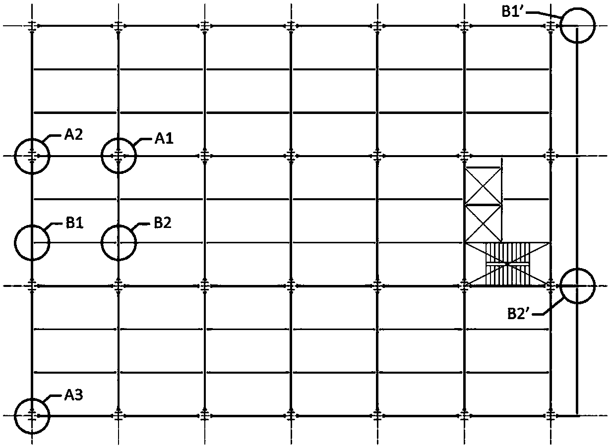
[0111] For a better understanding of the application, various aspects of the application will be described in more detail with reference to the accompanying drawings. It should be understood that these detailed descriptions are descriptions of exemplary embodiments of the application only, and are not intended to limit the scope of the application in any way. Throughout the specification, the same reference numerals refer to the same elements. The expression "and / or" includes any and all combinations of one or more of the associated listed items.

[0112] It will be understood that although the terms first, second, etc. may be used herein to describe various elements, components or sections, these elements, components or sections should not be limited by these terms. These terms are only used to distinguish one element, component or section from another element, component or section. Thus, for example, a first box-shaped sleeve, a first C-shaped sleeve, a first protrusion, a...


PUM


Abstract

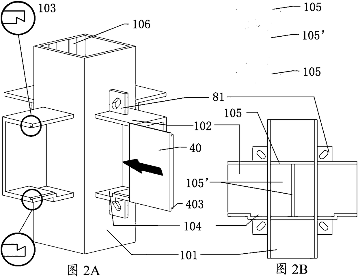
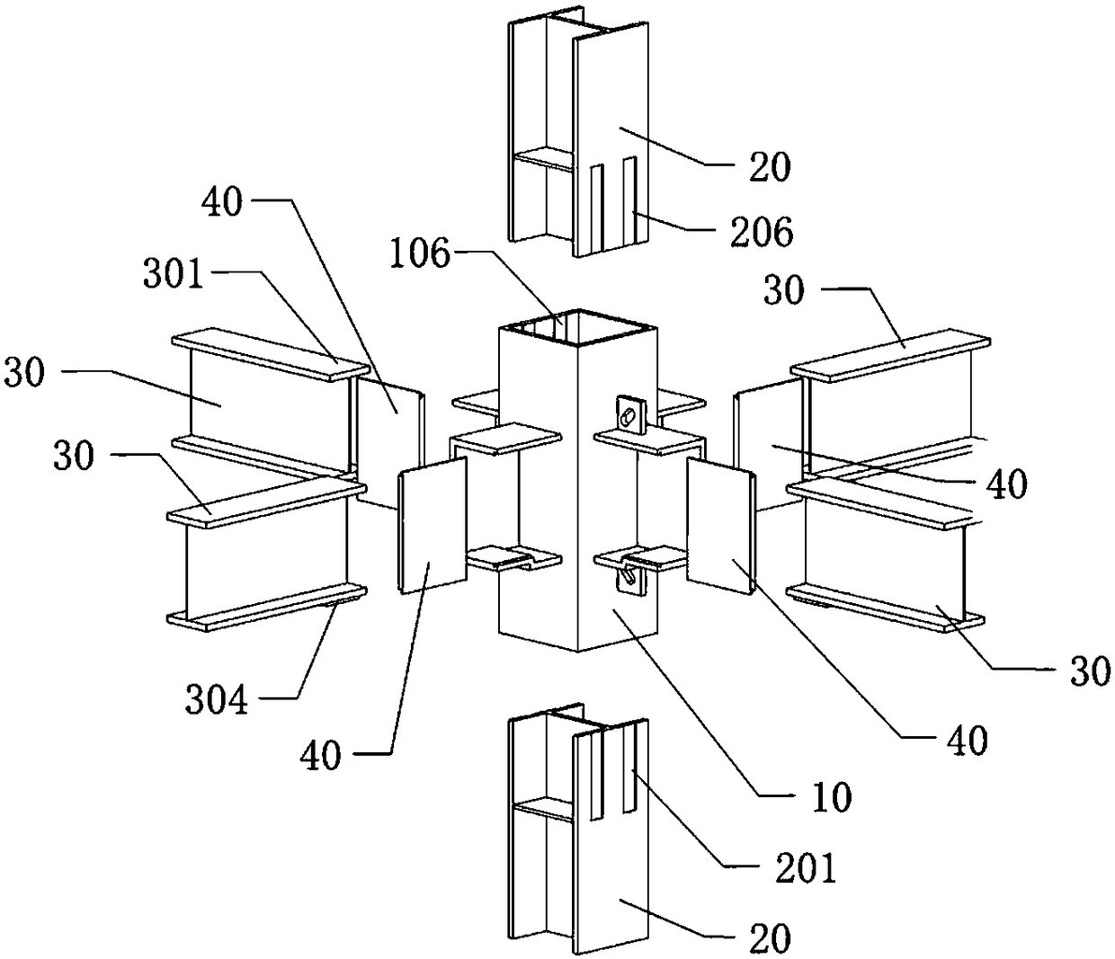
The present invention provides a prefabricated fabricated structure system and an assembling method thereof. The prefabricated fabricated structure system can be used for a steel structure, a reinforced concrete structure and a wood structure. When used for the steel structure, the prefabricated fabricated structure system comprises steel structure joints and related elements. The steel structurejoints and related elements further comprise beam-column connection sleeves, vertical columns, main beams and fixed steel plates for the main beams. The beam-column connection sleeves comprise first box-shaped steel tubes and first C-shaped sleeves vertically extending from the outer surfaces of the first box-shaped steel tubes. First wedge-shaped concave parts are arranged at the ends of the upper and lower flanges of the first C-shaped sleeves. The vertical columns are provided with column connection ends which are inserted into the first box-shaped steel tubes. The main beams are provided with main beam connection ends which are inserted into the first C-shaped sleeves. First wedge-shaped protruding parts matched with the first wedge-shaped concave parts of the first C-shaped sleeves ina mortise and tenon joint mode are arranged on the two sides of the fixed steel plates for the main beams. The application range of the beam-column connection sleeves of the prefabricated fabricatedsteel structure system can be further extended from the steel structure to the reinforced concrete structure and the wood structure.

Description

technical field [0001] This application relates to the technical field of structural engineering, specifically to a new type of prefabricated assembly structure system and its assembly method, and more specifically to a steel structure, reinforced concrete structure and wood structure that uses a similar mortise and tenon structure as the joint connection method of steel structures. Prefabricated structural system and assembly method thereof. Background technique [0002] The steel structure mainly connects the main structural components such as columns, main beams, secondary beams, and diagonal braces into a whole through connecting nodes. [0003] Currently the most commonly used joint connection methods include the use of high-strength bolts and welding. Usually steel components such as beams and columns and connecting plates are pre-processed in the steel structure processing plant, the connecting plates and stiffening plates are welded, and the bolt holes are pre-opene...

Claims


Application Information

Patent Timeline
Patent Type & Authority Applications(China)
IPC IPC(8): E04B1/24E04B1/58
CPCE04B1/2403E04B2001/2406E04B2001/2409E04B2001/2427E04B2001/2475
Inventor 喻德明吕文杰江锦正
Owner NEW WORLD CHINA LAND
Learn More