
MEMS (micro-electro-mechanical system) fully decoupled closed-loop gyroscope

A gyroscope and micro-mechanical technology, applied in gyroscope/steering sensing equipment, gyro effect for speed measurement, instrument and other directions, can solve the problems of affecting device measurement accuracy, orthogonal error interference signal, complex design structure, etc., and achieve good results The ability to resist cross-error interference, eliminate orthogonal error interference signals, and improve the effect of zero-bias stability indicators

Pending Publication Date: 2018-09-07
四川知微传感技术有限公司
View PDF17 Cites 26 Cited by
  • Summary
  • Abstract
  • Description
  • Claims
  • Application Information

AI Technical Summary

Problems solved by technology

[0003] However, the stability of the micromachined gyroscope index is one of the key bottlenecks hindering its practical application. The poor stability of the zero bias seriously hinders its application in the high-end field. There is a large mechanical coupling between the mode and the detection mode, which causes the output of the gyroscope to have a part of the orthogonal error interference signal, which affects the zero bias and stability indicators of the gyroscope.
At present, the method of structurally improving the bias stability of micromachined gyroscopes is mainly through decoupling design schemes, and semi-decoupling designs are often used. The advantage is that the design is relatively simple and the processing is easier, but this scheme cannot completely eliminate positive bias. The bias stability of micro-mechanical gyroscopes is still poor. In recent years, it has been reported that the full decoupling design scheme has greatly improved the bias stability index, but its design structure is complex and the chip The large area is not conducive to the miniaturization and integration of the device. At the same time, the sensitive mass may be reversed, which will eventually affect the measurement accuracy of the device.

Method used


Image

  • MEMS (micro-electro-mechanical system) fully decoupled closed-loop gyroscope
  • MEMS (micro-electro-mechanical system) fully decoupled closed-loop gyroscope
  • MEMS (micro-electro-mechanical system) fully decoupled closed-loop gyroscope

Examples


Embodiment Construction

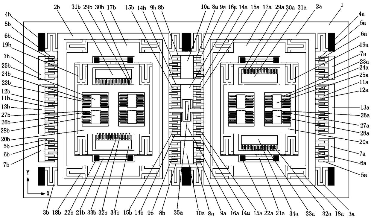
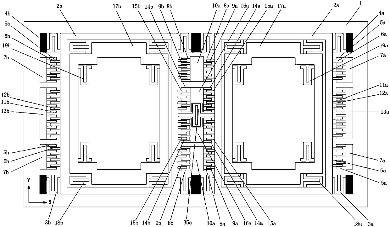
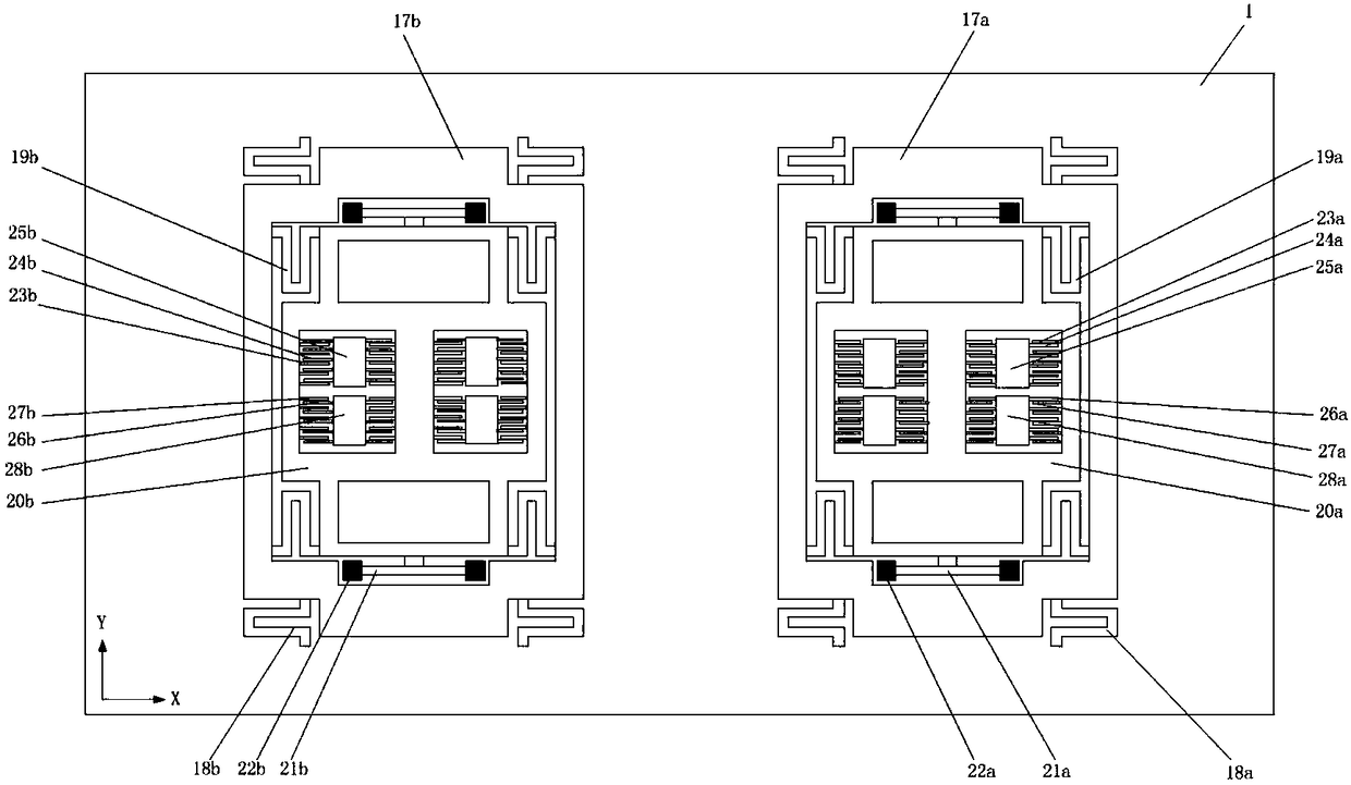
[0029]The invention provides a MEMS micromechanical fully decoupled closed-loop gyroscope, through the ingenious design of the gyroscope decoupling frame, the mechanical coupling between the driving mode and the detection mode can be completely eliminated, the generation of orthogonal error signals can be suppressed, and the improvement can be improved. The zero-bias stability index of the micro-mechanical gyroscope device, at the same time, the design structure is compact, the chip area is small, and the displacement of the gyroscope detection structure is limited by the closed-loop control method, which can prevent the detection mode sensitive mass from torsion due to large displacement, and the overall Good linearity and high measurement accuracy.

[0030] In order to understand the above-mentioned purpose, features and advantages of the present invention more clearly, the present invention will be further described in detail below in conjunction with the accompanying drawin...


PUM


Abstract

The invention discloses a MEMS (micro-electro-mechanical system) fully decoupled closed-loop gyroscope. The gyroscope comprises a substrate and a sensitive device layer, wherein an insulating layer isarranged between the substrate and the sensitive device layer; the sensitive device layer comprises a first substructure, a second substructure and a coupling connection beam; each of the first substructure and the second substructure comprises a driving frame, driving folding beams, driving decoupling beams, a Coriolis mass block, a detection frame, detection beams, detection decoupling beams, driving fixed comb teeth, driving movable comb teeth, driving detection fixed comb teeth, driving detection movable comb teeth, detection fixed comb teeth, detection movable comb teeth, force feedbackfixed comb teeth, force feedback movable comb teeth and anchor points. Generation of quadrature error signals is suppressed, and the zero bias stability index of the MEMS gyroscope is improved; the gyroscope has compact structure and small chip area, and can prevent a detection-mode sensitive mass from twisting due to larger displacement, thereby having good overall linearity and high measurementaccuracy.

Description

technical field [0001] The invention relates to the research field of micromechanical gyroscopes, in particular to a MEMS micromechanical fully decoupled closed-loop gyroscope. Background technique [0002] MEMS (Micro-Electro-Mechanical System) micro-mechanical gyroscope is an inertial device that uses the Coriolis effect to measure the rotational angular rate of the base. It is widely used due to its small size, light weight, high reliability, and easy mass production. In the consumer market, as well as high-end fields such as industrial control, aerospace, national defense and military, it has broad use value and market application prospects. [0003] However, the stability of micromachined gyroscope indicators is one of the key bottlenecks hindering its practical application. The poor stability of zero bias seriously hinders its application in high-end fields. There is a large mechanical coupling between the mode and the detection mode, resulting in a part of the orthog...

Claims


Application Information

Patent Timeline
IPC IPC(8): G01C19/5621
CPCG01C19/5621
Inventor 雷龙海周骏王龙峰王志山永启
Owner 四川知微传感技术有限公司
Learn More