Pile-supported type reinforced embankment three-dimensional deformation field visual test device and test method thereof

A reinforced embankment, three-dimensional deformation technology, applied in the direction of measuring devices, instruments, scientific instruments, etc., can solve the problems of uneven deformation of the water bag surface, inability to obtain the three-dimensional deformation field of the soil, inconvenient installation and disassembly, etc., to achieve saving Cost and time, the realization of visual observation, the effect of easy replacement

Active Publication Date: 2018-09-07
CHONGQING UNIV
View PDF7 Cites 10 Cited by
  • Summary
  • Abstract
  • Description
  • Claims
  • Application Information

AI Technical Summary

Problems solved by technology

[0004] Because the soil is non-transparent, the traditional photogrammetry method can only measure the deformation of the soil surface, and cannot observe the internal deformation of the soil.
If you want to measure the internal deformation of the pile-supported embankment, you need to bury the displacement measuring device in the embankment to obtain the deformation data. However, many model tests are small in size, and the measuring devices and cables buried in the soil will seriously interfere with the movement of the soil. Bearing performance, the data obtained are only scattered data of several feature points, and the three-dimensional deformation field inside the soil cannot be obtained
[0005] There is a transparent soil model test method in the prior art, but this method has many deficiencies: water bags are used to simulate f

Method used


Image

  • Pile-supported type reinforced embankment three-dimensional deformation field visual test device and test method thereof
  • Pile-supported type reinforced embankment three-dimensional deformation field visual test device and test method thereof
  • Pile-supported type reinforced embankment three-dimensional deformation field visual test device and test method thereof

Examples


Embodiment 1

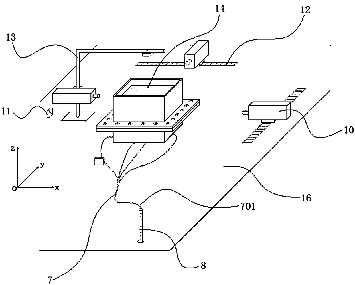
[0052]This embodiment discloses a three-dimensional deformation field visualization test device for a pile-supported reinforced embankment, including a model groove existing in an o-xyz orthogonal coordinate system, nine model piles 3 and nine pile caps 4 .

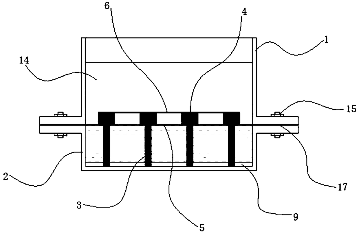
[0053] see figure 2 and image 3 , the model tank is made of transparent plexiglass, and the whole is a rectangular box. The mold tank can be divided into an upper mold tank 1 and a lower mold tank 2 .

[0054] The upper mold tank 1 is a rectangular frame as a whole. The lower end of this rectangular frame has an outer curl I101.

[0055] The lower mold tank 2 as a whole is a rectangular box. The upper end of this rectangular box has an outer crimp II 201 . A positioning plate 9 is arranged at the bottom of the lower mold tank 2 . see Figure 7 , there are 9 grooves 901 for the model pile 3 to be embedded on the surface of the positioning plate 9 . The positioning plate 9 is processed according to the test plan, ...

Embodiment 2

[0063] This embodiment discloses a three-dimensional deformation field visualization test device for a pile-supported reinforced embankment, including a model groove existing in an o-xyz orthogonal coordinate system, 16 model piles 3 and 16 pile caps 4 .

[0064] The model tank is made of transparent tempered glass, and the whole is a rectangular box. The mold tank can be divided into an upper mold tank 1 and a lower mold tank 2 .

[0065] The upper mold tank 1 is a rectangular frame as a whole. The lower end of this rectangular frame has an outer curl I101. A sealing gasket 17 is attached to the bottom of the outer curling I101. The gasket 17 is made of rubber material. The maximum side length of the inner cavity of the upper model groove 1 is 19cm, and the height is 22cm.

[0066] The lower mold tank 2 as a whole is a rectangular box. The upper end of this rectangular box has an outer crimp II 201 . The maximum side length of the cavity of the lower model groove 2 is 1...

Embodiment 3

[0075] This embodiment discloses a test method using the test device described in embodiment 1 or 2, comprising the following steps:

[0076] 1) Experimental design: read relevant literature, consult information, draw up a test plan, and determine the specific test parameters for each group of working conditions. Among them, the test parameters include the size of the model groove, the shape and size of the pile cap 4, the pile distance, the form of pile arrangement, the filling height, the relative compactness of the filling, and the displacement.

[0077] 2) Model making: Make a model according to the test plan. Clean the model tank and the model pile 3 to prevent the prepared transparent soil 14 from being polluted and affect the experimental results.

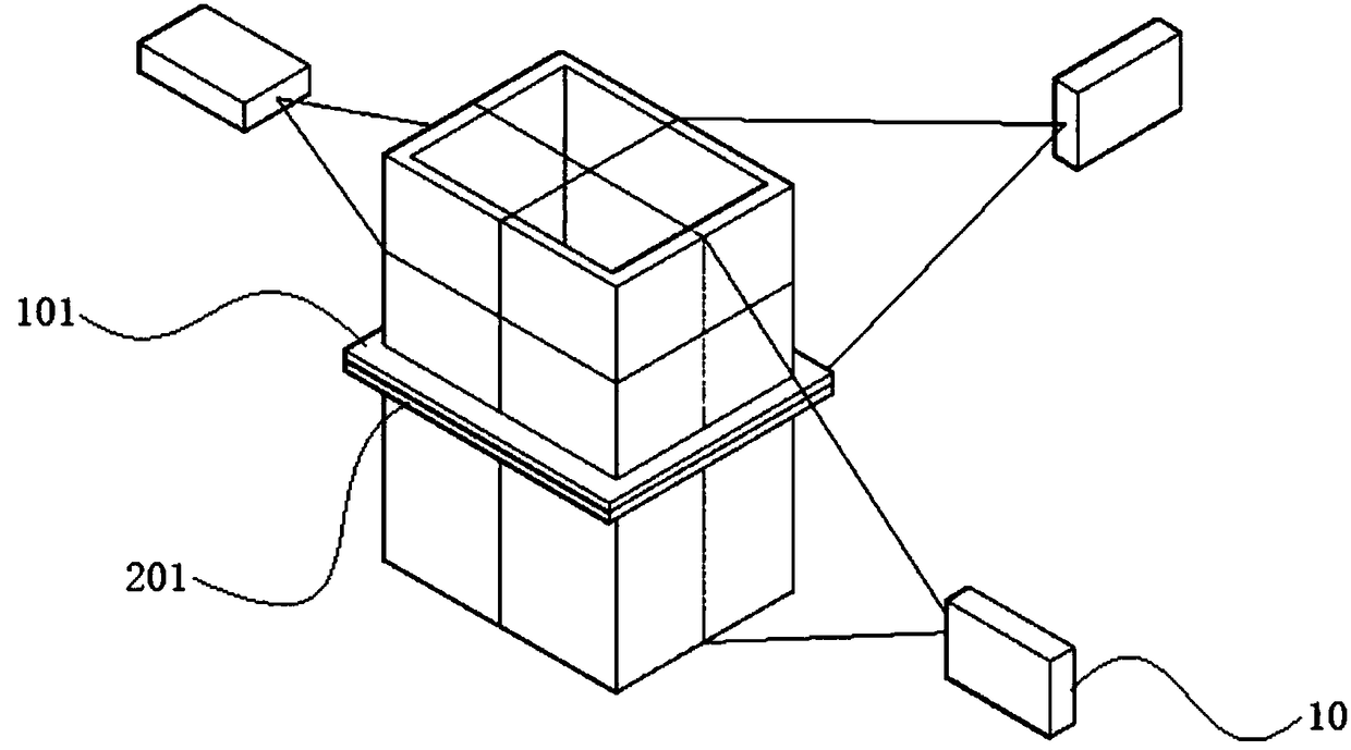
[0078] 3) Fix the lower model tank 2, the laser 10 and the high-speed CCD camera 11 on the optical table.

[0079] 4) Lay out model piles 3 .

[0080] 5) Close the drain valve 701 and inject water into the lower model tank ...


PUM

PropertyMeasurementUnit
Particle sizeaaaaaaaaaa
Dry densityaaaaaaaaaa

Abstract

The invention provides a pile-supported type reinforced embankment three-dimensional deformation field visual test device and a test method thereof. The test device includes a model groove, a plurality of model piles, and pile caps. The model groove is made of a transparent material and is a rectangular box as a whole. In operation, the model groove is placed on an optical table. The bottom of each model pile is inserted into the groove. The lasers emitted by three lasers forms three laser planes in transparent soil. During a test, a drain valve is controlled to discharge water in a lower model groove at a constant rate, and a settlement process of a soft soil layer under the self-weight of embankment fill soil is simulated. The test method of the test device includes the steps of test design, model making, model groove positioning, pile arrangement, soil mixing, testing and data processing. A settling mode of the device is consistent with the reality, and the device is safe and reliable, and cost-saving.

Description

technical field [0001] The invention relates to a model test technology in the field of foundation treatment, in particular to a three-dimensional deformation field visualization test device and test method of a pile-supported reinforced embankment. Background technique [0002] my country has a vast territory and varied geological conditions. There are a large number of soft soils distributed in coastal plains, deltas, banks of rivers and lakes, and valleys between mountains. When building expressways and high-speed railways, they have to pass through these areas because of the limited route selection. Soft soil usually has high water content, high compressibility, low bearing capacity, and some are rich in organic matter, and due to poor permeability, it is difficult to achieve a good consolidation effect in a short period of time. If it is not dealt with, it may cause excessive settlement of roads and railways, which will affect the use. [0003] Due to the existence of...

Claims


Application Information

Patent Timeline
IPC IPC(8): G01N33/00
CPCG01N33/00
Inventor 丁选明黄宇航吴琪张延玲彭宇
Owner CHONGQING UNIV
Why Eureka
Try Eureka