
Cabin body inner wall robot automatic milling processing device

An automatic milling and processing device technology, applied in the direction of metal processing equipment, manipulators, milling machine equipment, etc., can solve the problems of cabin body processing in place, many measurement points, and processing efficiency constraints, so as to ensure accuracy, processing flexibility, and simple and compact structure , start the effect quickly

Pending Publication Date: 2018-09-11
BEIJING HANGTIAN XINFENG MECHANICAL EQUIP
View PDF1 Cites 2 Cited by
  • Summary
  • Abstract
  • Description
  • Claims
  • Application Information

AI Technical Summary

Problems solved by technology

Its wall thickness is an important key technical indicator. At present, most of the cabins are cast to prevent forming, and the casting allowance is large and uneven. Due to the complex structure of the cabin cavity and poor machining flexibility of the machine tool, the inner walls of most complex cabins will interfere. It is impossible to directly process the cabin body in place. After the cabin machine tool is machined, it is necessary to manually polish the unprocessed parts of the cabin inner wall. During the grinding process, it is necessary to continuously use the thickness gauge to measure the wall thickness and continuously polish and correct until the wall thickness requirements are met. , the processing efficiency of the inner wall of the cabin directly restricts the cycle of the entire industrial processing and manufacturing
Due to the large area to be polished on the inner wall of the cabin, the efficiency of manual grinding is low, there are many measurement points, the quality risk is high, the working environment is poor, and the labor intensity is high. Especially the magnesium alloy dust is combustible. The dust and Noise pollution is a serious threat to the health and safety of operators

Method used


Image

  • Cabin body inner wall robot automatic milling processing device
  • Cabin body inner wall robot automatic milling processing device

Examples


Embodiment Construction

[0015] The present invention will be further elaborated below in conjunction with the accompanying drawings.

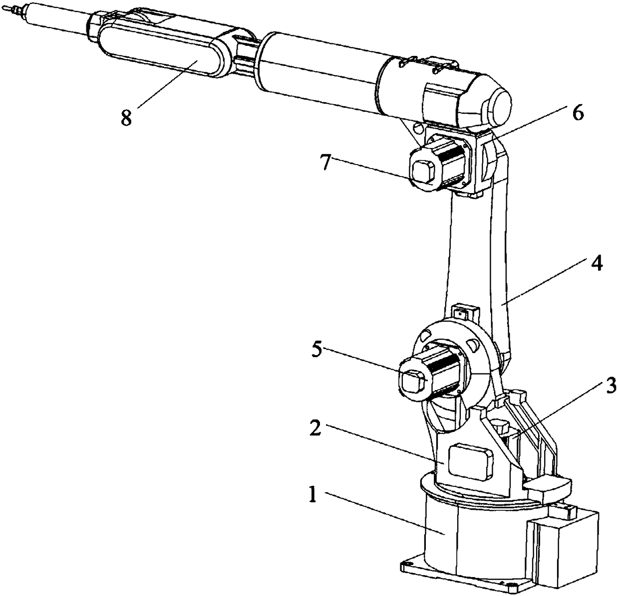
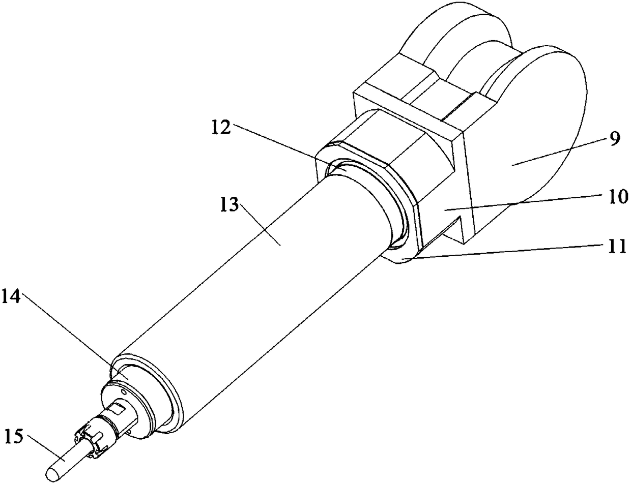
[0016] Such as Figure 1-2 As shown, a robot automatic milling device for a cabin inner wall of the present invention mainly includes a base 1, a turntable 2, a turntable motor 3, a boom 4, a boom motor 5, a box body 6, a forearm motor 7, and a forearm 8 , Wrist body 9, wrist body support 10, wrist body end cover 11, wrist body connecting flange 12, pneumatic main shaft 13, fixture 14, cutter 15. The turntable 1 and the turntable motor 3 are arranged on the base 1, and the turntable motor 3 drives the turntable 2 to rotate. The boom 4 and the boom motor 5 are arranged on the turntable 2, and the boom 4 is driven to rotate by the boom motor 5. The box body 6 and the small arm motor 7 are arranged on the boom 4, and the small arm 8 is arranged on the box body 6, and the small arm motor 7 drives the small arm 8 to rotate. The wrist body 9 is arranged between the forea...


PUM


Abstract

The invention provides a cabin body inner wall robot automatic milling processing device. The device includes a mechanical arm control system, a wrist body system and a main shaft system. The mechanical arm control system comprises a base, a rotating disk, a rotating disk motor, a large arm, a large arm motor, a box body, a small arm and a small arm motor; the wrist body system mainly comprises awrist body, a wrist body support, a wrist body end cover and a wrist body connection flange; and the main shaft system mainly comprises an air-operated main shaft, a fixture and a cutting tool. The device controls cutting tool operation through mechanical arms, achieves cabin body inner wall robot automatic milling processing, and has the advantages of simple structure and convenient installation.

Description

technical field [0001] The invention relates to a processing device for a barrel-shaped cabin body, in particular to a robot automatic milling processing device for the inner wall of the cabin. Background technique [0002] A circular barrel-shaped cabin as an important component of a product. Its wall thickness is an important key technical indicator. At present, most of the cabins are cast to prevent forming, and the casting allowance is large and uneven. Due to the complex structure of the cabin cavity and poor machining flexibility of the machine tool, the inner walls of most complex cabins will interfere. It is impossible to directly process the cabin body in place. After the cabin machine tool is machined, it is necessary to manually polish the unprocessed parts of the cabin inner wall. During the grinding process, it is necessary to continuously use the thickness gauge to measure the wall thickness and continuously polish and correct until the wall thickness requireme...

Claims


Application Information

Patent Timeline
Patent Type & Authority Applications(China)
IPC IPC(8): B23C3/00B25J9/12B25J11/00
CPCB23C3/00B25J9/126B25J11/005
Inventor 张逊陈芳琪张旭尹国涛宫虎胡海博
Owner BEIJING HANGTIAN XINFENG MECHANICAL EQUIP
Learn More