Adjustable metamaterial phase shifter based on active device

A technology of active devices and metamaterials, applied in the direction of waveguide devices, electrical components, circuits, etc., can solve the problems that the working frequency cannot be adjusted, limit the application of metamaterial structures, etc., and achieve the effect of compact structure

Inactive Publication Date: 2018-09-11
DONGHUA UNIV
2 Cites 0 Cited by

AI-Extracted Technical Summary

Problems solved by technology

[0004] Due to the limitation of the dispersion and dissipation of the metamaterial itself, the metamaterial can only work in a narrow frequency range in actual experiments; in addition, the ...

Method used

[0041] Both the varactor diode and the active inductance must achieve a sufficient quality factor (Q) at the design frequency, which sets an upper limit on the operating speed of the phase shifter. The operating frequency of active inductors is as high as several G or ten...

Abstract

The invention relates to an adjustable metamaterial phase shifter based on an active device. The adjustable metamaterial phase shifter comprises a metamaterial unit for realizing a negative refractiveindex, and a series capacitor and a parallel inductor on a metamaterial unit transmission line; the overall phase shift value is a combination of the metamaterial unit and a phase shift unit composedof a capacitive inductor. The invention is a compact microwave and millimeter wave band phase shifter realized by an active device. The phase shifter can realize negative phase shifting characteristics without going through the entire cycle, and can be applied to phased array radars and communication systems. Moreover, the phase shifter does not use the method that the conventional phase shiftersset different propagation paths to generate a phase shift through switches, and the structure is more compact.

Application Domain

Waveguide type devices

Technology Topic

Phase shiftedWave band +14

Image

  • Adjustable metamaterial phase shifter based on active device
  • Adjustable metamaterial phase shifter based on active device
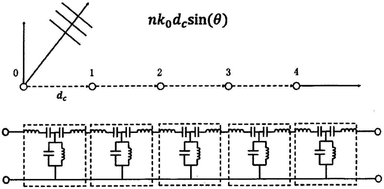
  • Adjustable metamaterial phase shifter based on active device

Examples

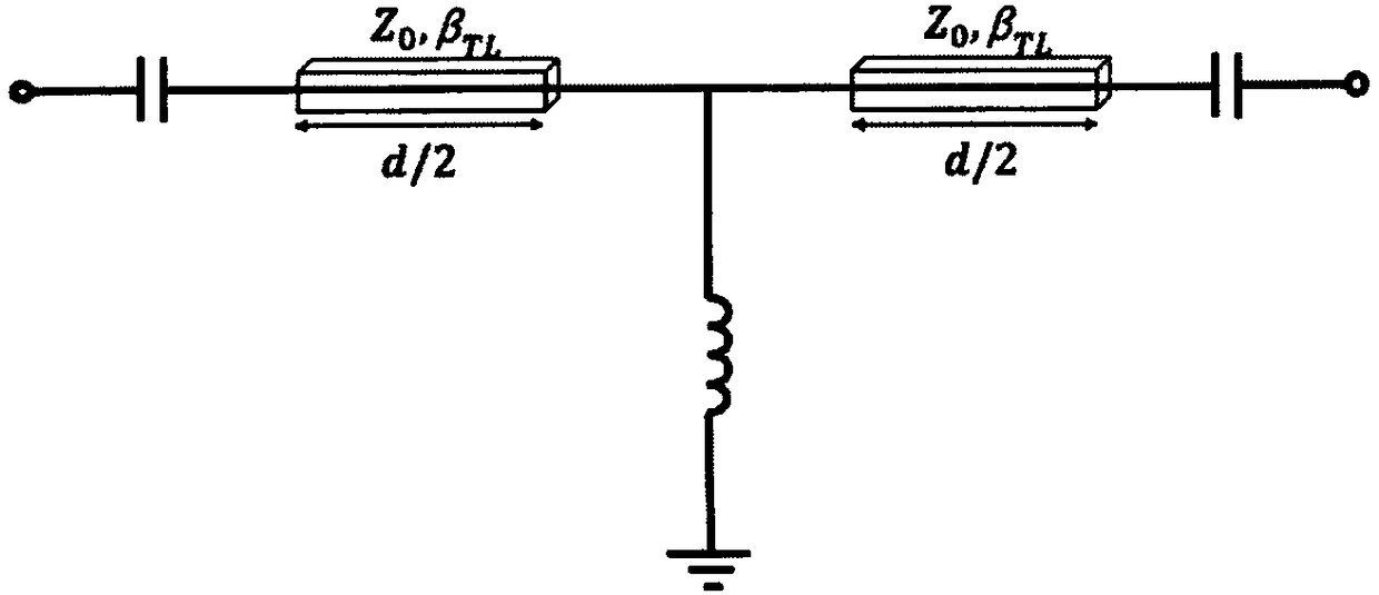
  • Experimental program(1)

Example Embodiment

[0020] In order to make the present invention more comprehensible, preferred embodiments are described below in detail with accompanying drawings.
[0021] The phased array system (applicable to radar, communication and other systems) is based on the ability to phase shift microwave and millimeter wave signals so as to achieve antenna beam scanning. The basic idea of ​​using metamaterial elements to realize a phased array system is: first, according to the requirements of phased array antenna beam scanning, the amplitude and phase modulation parameters of the antenna radiating element are allocated; then the microstrip line embedded with the metamaterial configuration is used to optimize the super Material voltage tuning parameters to achieve the requirements of phased array antennas, the basic block diagram is as follows figure 1 As shown, figure 1 Where n represents the number of phased array radiating elements, k 0 Represents the amplitude weighting coefficient of the radiating element, d c Indicates the distance between radiating elements, and θ represents the feed phase difference between adjacent radiating elements. figure 1 The structure shown includes a phase shifter implemented with multiple metamaterial units.
[0022] The metamaterial structure can realize the positive refractive index (PRI) and negative refractive index (NRI) of the metamaterial transmission line. This metamaterial transmission line can be used to construct a high-frequency phase shifter, and this structure can be constructed with positive and negative directions Wideband compact phase shifter.
[0023] figure 2 It is a phase shifter unit realized by metamaterials. It consists of a microstrip line equipped with a series capacitor and a parallel inductor. This is equivalent to cascading the PRI line and the NRI line, which causes the phase shift of the compensated propagation signal. Using periodic analysis, it can be shown that the phase shift value of the unit cell can be given by equation (1):
[0024]
[0025] Where θ TL Is the phase lag caused by a section of the microstrip line, and its value can be expressed as:
[0026] θ TL = Β TL d/2.
[0027] Where β π Represents the phase velocity of the wave, and d represents the length of the transmission line.
[0028] In order to maintain the characteristic impedance Z of the metamaterial transmission line 0 Matching, we will enter the reflection coefficient (S 11 ) Is equal to zero, and the relationship between inductance, capacitance and phase shift in frequency can be obtained:
[0029]
[0030] To simplify the calculation, assuming that the signal propagates in the microstrip line with a small phase shift, which is approximately zero, the matching condition (the above formula) can be approximated as:
[0031]
[0032] The same result can be obtained by studying the stop band of the periodic structure and finding the conditions to eliminate the stop band near the zero phase shift region. Under this matching condition, the phase can be approximated as:
[0033]
[0034] This means that both positive and negative phase shifts can be realized by a single cell, without having to undergo a complete phase rotation like traditional low-pass or high-pass. In addition, the amount of phase shift can be achieved by adjusting and changing the value of the loaded elements (L and C), but to keep the transmission line matching, the two elements must be adjusted at the same time to satisfy formula (3).
[0035] If the series capacitance is only in C=(C max +C min The inductance value selected at )/2 to match the phase shifter changes, which will cause the phase tuning range Δφ C Smaller, given by:
[0036]
[0037] Where: r=C max /C min , If both L and C are tuned to meet the matching conditions, the phase tuning range Δφ C-L Expressed as:
[0038]
[0039] It can be seen from the above formula that changing the values ​​of L and C to achieve matching can achieve different phase shifts.
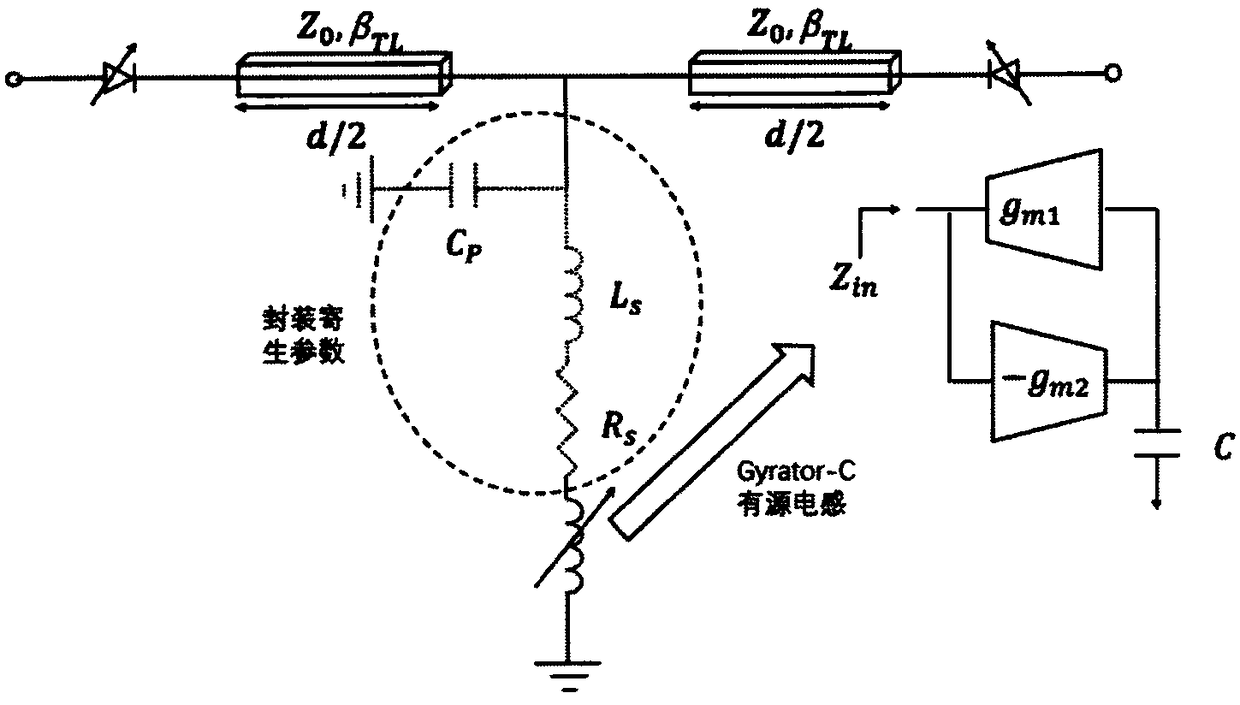
[0040] image 3 The designed metamaterial phase shifter unit based on active adjustable device is shown. The adjustable capacitor is realized by a varactor diode, in which the reverse voltage of the varactor diode controls its capacitance. On the other hand, use active circuits to implement electronic tunable inductors; most of the implementations of active inductors are based on the gyrator-C architecture, such as image 3 Shown. Common equivalent inductance through L=C/g m1 g m2 Approximately, by adjusting the transconductance g m1 And g m2 So as to realize the adjustment of the inductance value.
[0041] Both the varactor diode and the active inductor must achieve a sufficient quality factor (Q) at the design frequency, which sets the upper limit of the operating speed of the phase shifter. The operating frequency of active inductors is up to several G or more than tens of G Hz, which can be realized by using 0.1μ InGaAs/InP High Electron Mobility Transistor (HEMT). The active tunable metamaterial shifter realized by the above method can be applied to the microwave or millimeter wave frequency band and has a wide range of application prospects.

PUM

no PUM

Description & Claims & Application Information

We can also present the details of the Description, Claims and Application information to help users get a comprehensive understanding of the technical details of the patent, such as background art, summary of invention, brief description of drawings, description of embodiments, and other original content. On the other hand, users can also determine the specific scope of protection of the technology through the list of claims; as well as understand the changes in the life cycle of the technology with the presentation of the patent timeline. Login to view more.

Similar technology patents

Preparation method of CaCu3Ti4O12 ceramic

Owner:NORTHWESTERN POLYTECHNICAL UNIV

Connector locking and electromagnetic unlocking device

ActiveCN101908691Acompact structurereliable unlock
Owner:GUIZHOU SPACE APPLIANCE CO LTD

Classification and recommendation of technical efficacy words

  • compact structure

Smart home system based on internet of things cloud computing

Owner:中国联合网络通信有限公司物联网研究院

Bionic underwater chelonian robot

InactiveCN101134500ACloselycompact structure
Owner:HARBIN ENG UNIV
Why Eureka
Try Eureka