Clamping stages and machine tools for thin wafer processing

A wafer and stage technology, applied to machine tools, metal processing equipment, grinding machines, etc., which are suitable for grinding workpiece planes, can solve the problems of reduced production efficiency, increased processing costs, and increased procedures, so as to improve production efficiency and save High cost and high efficiency

Active Publication Date: 2019-12-13
NANTONG XINRUIT MACHINERY CO LTD
View PDF7 Cites 0 Cited by
  • Summary
  • Abstract
  • Description
  • Claims
  • Application Information

AI Technical Summary

Problems solved by technology

[0003] It is not difficult to see that although this prior art can better solve the technical problem of weak and fragile thin wafer wafers, it additionally increases the loading wafer, which not only increases the process, reduces the production efficiency, but also increases the production efficiency of the wafer. Most of the wafers use engineering plastic boards, which are discarded directly after the functional wafers are cut. Therefore, the above-mentioned carrier wafers as one-time consumables will obviously lead to an increase in processing costs, which is not conducive to the popularization of mass production.
[0004] In addition, there are carrier wafers that can be recycled multiple times in the prior art, but the functional wafers in the prior art often use cleaning agents in the process of removing bonding glue and other processes, so this type of wafer can be used multiple times. The number of times the carrier wafer can be used is also greatly limited, so there is also the problem of high processing costs

Method used


Image

  • Clamping stages and machine tools for thin wafer processing
  • Clamping stages and machine tools for thin wafer processing
  • Clamping stages and machine tools for thin wafer processing

Examples


Embodiment 1

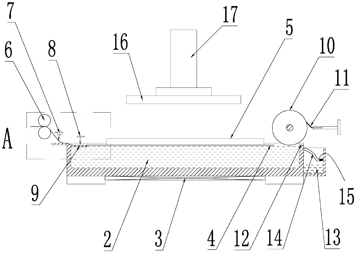
[0028] As a preference, the above-mentioned clamping stage includes a tank body 1, a magnetorheological fluid 2 is arranged in the tank body 1, and a bottom for driving the magnetorheological fluid 2 to solidify or reset to a fluid state is provided at the bottom of the tank body 1. The excitation device 3, the excitation device 3 refers to a device for generating a magnetic field, the magneto-rheological fluid 2 is solidified by the magnetic field, and when the excitation device 3 is powered off so that the magnetic field disappears, the magneto-rheological fluid 2 is reset again fluid state. The tank body 1 is provided with a paper feeding mechanism, and the paper feeding mechanism periodically supplies a single sheet of paper 4 into the tank body 1, and the paper sheet 4 floats on the liquid surface of the magnetorheological fluid 2. A paper pumping mechanism is provided on the other side of the tank body 1 away from the paper feeding mechanism. When the wafer 5 to be proce...

Embodiment 2

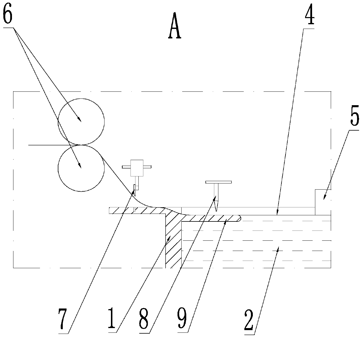
[0030] The general structure is the same as that of Embodiment 1, the difference is that the paper feeding mechanism includes a driving roller set 6 and a cutter assembly 7 for cutting paper, and the driving roller set 6 clamps the strip-shaped paper and drives the strip The shaped paper moves along its own length direction. The cutter assembly 7 is set on the tank body 1 and is located between the driving roller group 6 and the tank body 1. The strip-shaped paper is cut by the cutter assembly 7 to form several sheets. paper sheets 4, and each paper sheet 4 floats on the liquid surface of the magnetorheological fluid 2 in the tank body 1 in sequence.

[0031] Specifically, the driving roller set 6 includes a driving roller and a driven roller, the axes of the driving roller and the driven roller are parallel to each other, and a clamping space for clamping paper is formed between the driving roller and the driven roller. The above-mentioned driving rollers and driven rollers a...

Embodiment 3

[0034] The general structure is the same as that of Embodiment 2, the difference is that: the tank body 1 is provided with a nozzle 8, the nozzle 8 is located on the side of the cutter assembly 7 close to the inner cavity of the tank body 1, and the cutter assembly 7 is formed by shearing The paper sheet 4 floats on the liquid surface of the magnetorheological fluid 2 after being sprayed by the nozzle 8 . Specifically, the cutter assembly 7 includes a cutter and a knife frame, the knife frame is fixed to the tank body 1, and the knife frame is provided with a driving cylinder for driving the cutter to move.

[0035] Preferably, the nozzle 8 sprays water mist for wetting the paper sheet 4 .

[0036] Further, the nozzle 8 sprays a liquid bonding glue, through which the wafer 5 is bonded to the cured magnetorheological fluid 2 , that is, bonded.


PUM


Abstract

The invention discloses a clamping carrying table for processing of thin wafers. The clamping carrying table for processing of thin wafers comprises a trough, wherein the inside of the trough is provided with magnetorheological fluid; an excitation device which is used for driving the magnetorheological fluid to be solidified or to reset to be in a fluid state is arranged on the bottom of the trough; a paper conveying mechanism is arranged on the trough, and periodically supplies single pieces of paper into the trough; the paper floats on the surface of the magnetorheological fluid; and a paper drawing mechanism is arranged on the other side, which is away from the paper conveying mechanism, of the trough. When a wafer to be processed is placed on paper, the paper drawing mechanism draws the paper so that the paper is drawn away from space between the wafer and the surface of the magnetorheological fluid. By the provided clamping carrying table for processing of thin wafers, a functional wafer can be fixed without a carrying wafer, the strength of the functional wafer is high, the breakage rate is low in a processing course, and the yield of final products is high.

Description

technical field [0001] The invention relates to the technical field of wafer processing, in particular to a clamping platform and a machine tool for thin wafer processing. Background technique [0002] Thin wafers, especially thin wafers with a thickness less than 5mm, often need to be temporarily bonded to a carrier wafer during processing, so as to improve the strength of the functional wafer and facilitate processing, such as Thinning and grinding, etching, cutting, etc., and finally the functional wafer and the carrier wafer are separated to complete the processing of the functional wafer. [0003] It is not difficult to see that although this prior art can better solve the technical problem of weak and fragile thin wafer wafers, it additionally increases the loading wafer, which not only increases the process, reduces the production efficiency, but also increases the production efficiency of the wafer. Most of the wafers use engineering plastic boards, which are discar...

Claims


Application Information

Patent Timeline
Patent Type & Authority Patents(China)
IPC IPC(8): B24B7/22B24B41/06B24B27/00B24B1/00B24B55/00B24B57/02
CPCB24B1/005B24B7/228B24B27/0015B24B41/068B24B55/00B24B57/02
Inventor 韩赛
Owner NANTONG XINRUIT MACHINERY CO LTD
Why Eureka
Try Eureka